


10
OPERATION
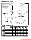
Lack of primary air will cause soft yellow-tipped flames. Excess
primary air produces short, well-defined flames with a tendency
to lift off the burner ports. Proper operation with natural gas
provides a soft blue flame with a well-defined inner core.
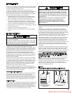
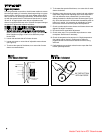
To increase primary air, loosen the manifold mounting screws
and tap the manifold away from the mixer tubes until yellow-
tipped flames disappear. See Figure 14. To decrease primary
air move the manifold closer to the mixer tubes until flames no
longer lift from burner ports, but being careful not to cause
yellow tipping. Retighten manifold mounting screws after
adjustment.
P
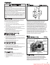
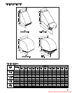
ropane Gas Flame Control
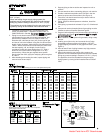
Adjustable primary air shutters are attached to the orifices on
the gas manifold for units equipped for propane gas operation.
See Figure 15.
A
n optimum flame will show a slightly yellow tip
.
Prior to flame adjustment, operate unit heater with casing
closed for at least five minutes. Then lower hinged bottom and
adjust primary air shutters. Loosen wing screws and push
shutters forward to reduce primary air until yellow flame tips
appear. Then increase primary air until yellow tips diminish to
just a slightly yellow tip and a clean blue flame with a well-
defined inner cone appears.
It may also be necessary to adjust the manifold position in
addition to adjusting air shutters to obtain proper flame. Follow
the instructions under "Natural Gas Flame Control" for adjusting
the manifold.
I
nput Adjustments
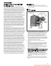
The gas pressure regulator (part of the combination gas control)
is adjusted at the factory for average gas conditions. It is
important that gas be supplied to the heater in accordance with
the input rating stamped on the serial plate. Actual input should
be checked and necessary adjustments made after the heater is
installed. Over-firing, a result of too high an input, reduces the
life of the unit, and increases maintenance. Under no
circumstances should the input exceed that shown on the rating
plate.
Input can be determined by the meter-timing method provided
other gas equipment connected to the meter is off during the
test. If this is not possible, use the pressure method.
(
A) Meter Timing Method
1. Shut off all other gas-burning equipment, including other
pilot lights served by the gas meter.
2. Start the heater and determine the number of seconds it
takes to consume 1 cu. ft. of gas. Two basic formulas are
useful:
F1 = 3600 C/T
F2 = F1/C
where:
F1 = input to heater, Btuh.
F2 = input to heater, cu. ft. per hr.
C = heating value of gas, Btu per cu. ft.
T = time to consume 1 cu. ft. of gas in sec.
The heating value of gas may be determined from the local
utility or gas dealer.
These are representative values:
GAS
Btu per cu. ft.
Natural 1000-1150
Propane 2500
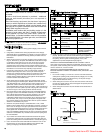
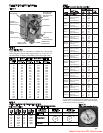
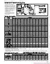
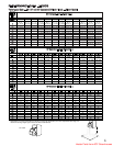
3.
If the seconds for 1 cu. ft. are more (input less) than shown in
Table 5 for model being tested, locate the combination gas
control and pressure regulator adjustment screw (see Figure
8). Remove the cap screw from the pressure regulator and
make one clockwise turn at a time on the adjustment screw
until the correct time is obtained. If the seconds are less (input
greater) than indicated in the table, follow the same procedure
in a
c
ounter-clockwise
direction.
If the correct number of seconds cannot be obtained check
orifice size. Correct orifices can be obtained from Modine
Manufacturing Company, Buena Vista, Virginia. When
requesting orifices, state type of gas, heating value, and its
specific gravity. Also give model number of unit.
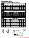
For example, if the input to the heater is 100,000 Btuh and the
heating value of the gas is 1000 Btu per cu. ft., then, by the
second formula, the input is 100 cu. ft. per hr. Table 4 indicates the
time for one revolution of various size meter dials with various
input rates. If a 1 cu. ft. meter dial is used, we proceed down the
cu. ft. column to 100 cu. ft. per hr. and then horizontally to the left
to determine a time of 36 seconds for one revolution of the dial.
Similarly, if the 1/2 cu. ft. dial is used, we determine a time of 18
seconds for one revolution at the required input.
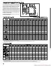
(B) Pressure Method
The pressure method determines input by measuring the
pressure of the gas in the manifold in inches of water.
1. Determine correct manifold pressure from Table 4.
2. Locate combination gas control.
3. Move gas control knob (or lever) to off.
4. Remove the 1/8" pipe plug in outlet pressure tap in
combination gas control (see Figure 9) and attach water
manometer or “U” tube which is at least 12" high.
5. Follow lighting instructions and turn thermostat up to get unit
to fire.
6. If pressure as indicated by “U” tube is less than 1/2" higher
or lower than indicated in Table 4, adjust regulator as
described under “Meter-Timing Method,” Step 3.
If pressure as indicated by “U” tube is more than 1/2" higher
or lower than indicated in Table 4, check inlet pressure at
unit. The inlet pressure should be 6"-7" W.C. pressure on
natural gas and 12"-14" W.C. on propane gas.
After adjustment move gas control knob (or lever) to off and
replace 1/8" pipe plug. With the plug in place, follow the lighting
instructions to put unit back in service.
CAUTION
Check the gas inlet pressure at the unit upstream of the
combination gas control. The inlet pressure should be 6"-7"
W.C. on natural gas or 12"-14" W.C. on propane. If inlet
pressure is too high, install an additional pressure regulator
upstream of the combination gas control.
Important
– Inlet pressure and manifold pressure must be
checked with unit in operation when making final adjustments.
Checking Input Rate
Heater Parts from ACF Greenhouses