


7
INSTALLATION
Installation of Blower Models (BAE UNITS)
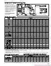
Determining Blower Speed
The drive assembly and motor on all gas-fired blower unit
heaters are factory assembled. The adjustable motor sheave
has been pre-set to permit operation of this unit under average
conditions of air flow and without any external static pressure.
The motor sheave should be adjusted as required when the unit
is to be operated at other than average air flows and/or with
external static pressures. Adjustment must always be within the
performance range shown on pages 18 and 19 and the
temperature rise range shown on the unit’s rating plate.
To determine the proper blower speed and motor sheave turns
open, the conditions under which the unit is to operate must be
known. If the blower unit is to be used without duct work,
nozzles or filters, the only criteria for determining the motor
sheave turns open and blower speed is the amount of air to be
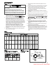
delivered. The performance tables for blower models are shown
on pages 18 and 19. As an example, a model BAE 350 unit,
operating with no external static pressure, that is, no duct work,
nozzles, etc., and is to deliver an air volume of 6481 cfm (cfm =
cubic feet of air per minute) requires that the unit be supplied
with a 5 hp motor, a C116 drive, and the drive sheave must be
set at 3 turns open to achieve a blower speed of 940 rpm (see
performance table for units with or without blower enclosure,
page 18). See "Blower Adjustments" on page 8 for setting of
drive pulley turns open.
If a blower unit is to be used with ductwork or nozzles, etc., the
total external static pressure under which the unit is to operate,
and the required air flow must be known before the unit can be
properly adjusted. Any device added externally to the unit, and
which the air must pass through, causes a resistance to air flow.
This resistance is called pressure loss. The total of the pressure
losses must be determined before adjusting the blower speed.
If Modine filters are used, the expected pressure loss through
the filters is included in the performance data on page 19. If
Modine supplied discharge nozzles are used, the expected
pressure drop of the nozzles can be found footnoted at the
bottom of page 14. If filters, nozzles or ductwork are to be used
with the unit, and they are not supplied by Modine, the design
engineer or installing contractor must determine the pressure
loss for the externally added devices or ductwork to arrive at the
total external static pressure under which the unit is to operate.
Once the total static pressure and the required air flow are
known, the operating speed of the blower can be determined
and the correct motor sheave adjustments made. As an
example, let's say, a model BAE 350 is to be used with a
Modine supplied blower enclosure and Modine supplied filters
attached to someone else's ductwork. The unit is to move 6481
cfm or air flow against an external static pressure of 0.2" W.C.
Entering the performance table on page 19 (Blower models with
filters) for a BAE 350, at 6481 cfm and 0.2" W.C. static
pressure, it is seen that the unit will require a 5 hp motor using a
C116 drive, and the motor sheave should be set at .5 turns
open to achieve a blower speed of 1055 rpm. You can see this
example differs from similar conditions in paragraph 2 by the
number of turns open and a higher rpm, which is needed to
overcome the added external static pressure from the filters.
T
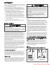
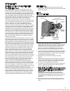
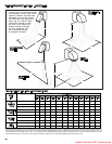
o Install (Figure 5):
1. Remove and discard the motor tie down strap and the
shipping block beneath the belt tension adjusting screw (Not
used on all models.)
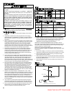
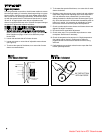
2. Adjust motor adjusting screw for a belt deflection of
approximately 3/4" with five pounds of force applied midway
between the sheaves (refer to Figure 6a). Since the belt
tension will decrease dramatically after an initial run-in
period, it is necessary to periodically re-check the tension.
Excessive tension will cause bearing wear and noise.
3. The blower bearings are lubricated for life; however, before
initial unit operation the blower shaft should be lubricated at
the bearings with SAE 20 oil. This will reduce initial friction
and start the plastic lubricant flowing.
4. Make electrical connections according to the wiring
diagram.
5. Check rotation of the blower. Motor should be in clockwise
rotation when facing motor pulley. If rotation is incorrect,
correction should be made by interchanging wiring within
the motor. See wiring diagram on the motor.
6. The actual current draw of the motor should be determined.
Under no condition should the current draw exceed that
shown on the motor rating plate.
7.
I
t is the installers responsibility to adjust the motor sheave to
provide the specified blower performance as listed on pages
18 & 19 for blower settings different from the factory set
performance
. The drive number on the unit may be
identified by referring to the Power Code number on the
serial plate of the unit (see page 28 for model number
nomenclature) and matching that number with those shown
on page 25. From the listing, the drive number can be
determined.
8. Blower sheave and motor sheave should be measured to
assure correct drive is on unit. Refer to page 26 for drive
sizes.
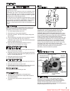
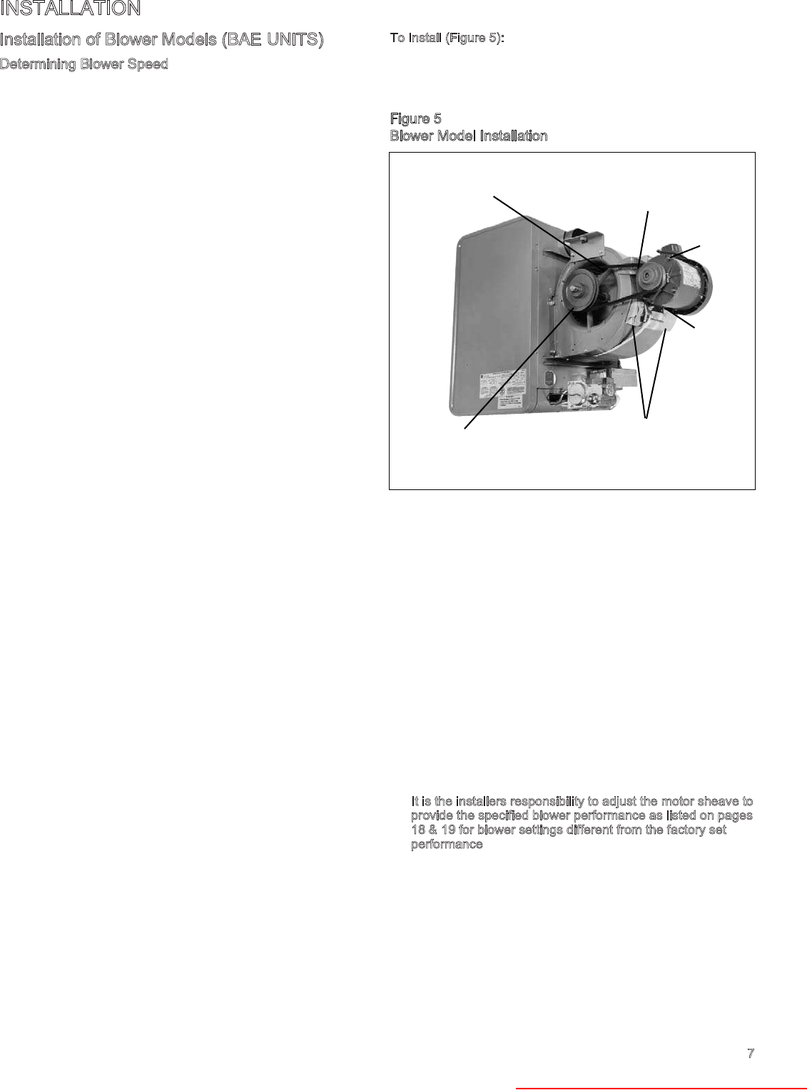
Figure 5
Blower Model Installation
MOTOR MOUNTING
BRACKET
MOTOR SHEAVE
(MOVEABLE FACE TO OUTSIDE)
OIL CUPS
UP
MOTOR
ADJUSTMENT
SCREW
TIE DOWN STRAP
& BLOCK FOR
SHIPPING ONLY
BLOWER
SHEAVE
Heater Parts from ACF Greenhouses