


Wiring
All field installed wiring must be done in accordance with the
National Electrical Code ANSI/NFPA 70 – Latest Edition or
Canadian Electrical Code CSA C22.1 Part 1 or local codes. Unit
must be electrically grounded according to these codes. See
wiring diagram shipped with unit. For optional wiring diagrams
see Bulletin 6-443.
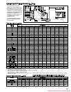
The power to these unit heaters should be protected with a
circuit breaker. Units for use with single-phase electric power,
should be provided with a manual motor starter, having properly
sized overload protection. Units for use with three-phase
electric power must be provided with a motor starter having
properly sized overload protection.
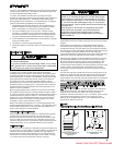
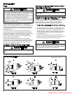
Location of thermostat should be determined by heating
requirements and be mounted on an inside wall about 5' above
floor level where it will not be affected by heat from the unit or
other sources, or drafts from frequently opened doors. See
instructions packed with thermostat.
I
nstallation of Blower Models (BAE UNITS)
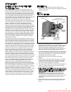
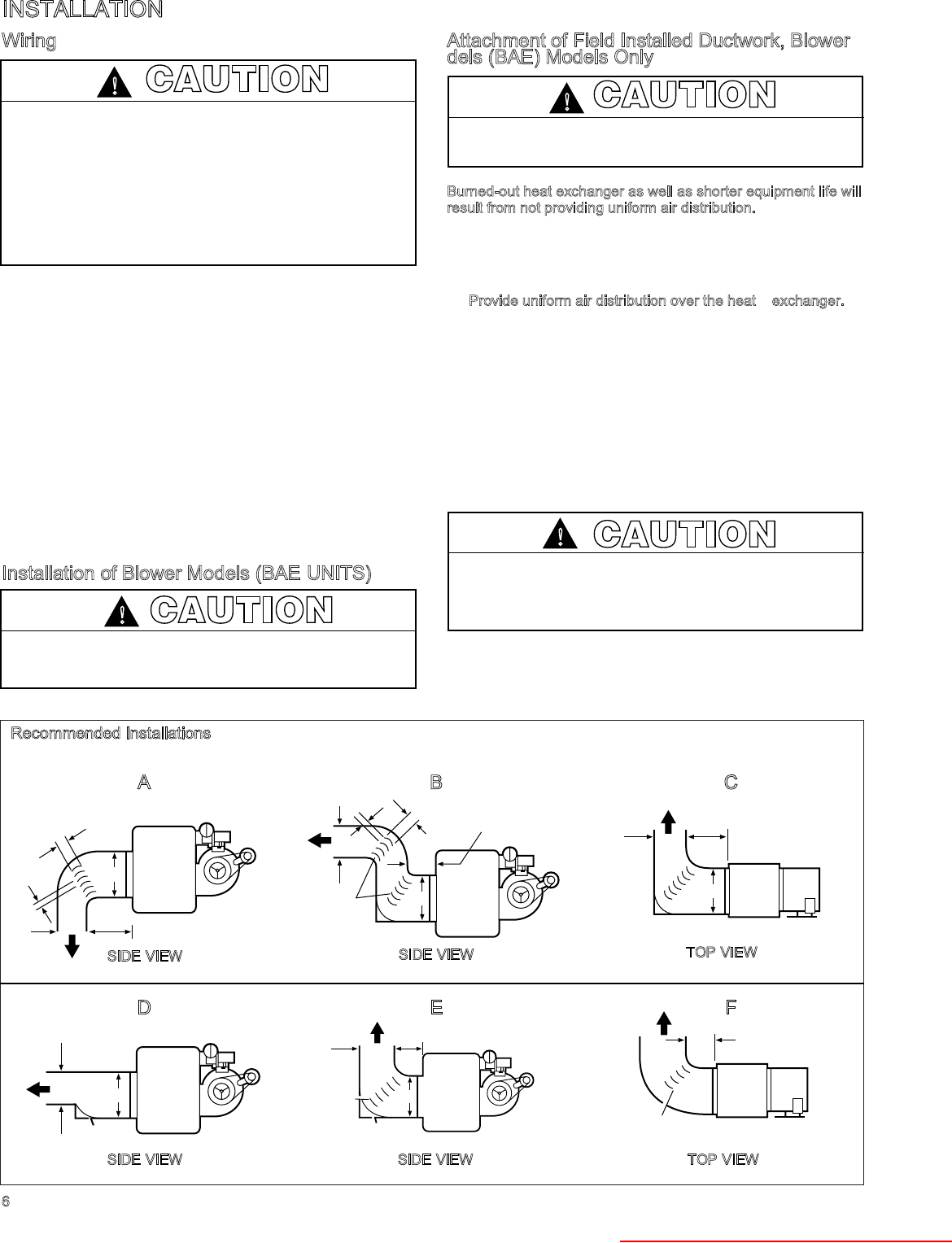
Attachment of Field Installed Ductwork, Blower
dels (BAE) Models Only
Burned-out heat exchanger as well as shorter equipment life will
result from not providing uniform air distribution.
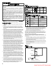
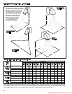
When installing heater always follow good duct design practices
for even distribution of the air across the heat exchanger.
Recommended layouts are shown below. When installing
blower units with ductwork the following must be done.
1.
P
rovide uniform air distribution over the heat exchanger.
Use turning vanes where required. See figures below.
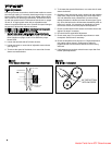
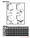
2. Provide removable access panels in the ductwork on the
downstream side of the unit heater. These openings should
be large enough to view smoke or reflect light inside the
casing to indicate leaks in the heat exchanger and to check
for hot spots on exchanger due to poor air distribution or
lack of sufficient air.
3.
If ductwork is connected to the rear of the unit use Modine
blower enclosure kit or if using field designed enclosure maintain
dimensions of blower enclosure as shown on page 12.
6
A
BAFFLE
B
12"
MIN.
A
B
BAFFLE
TURNING
VANES
12" MIN.
B
3" MAX.
TURNING
VANES
3" MIN.
A
A
3" MIN.
12"
MIN.
3" MAX.
TURNING
VANES
12"
B
BAFFLE
A
B
12"
MIN.
12"
MIN.
TURNING
VANES
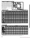
I
NSTALLATION
Recommended Installations
SIDE VIEW
SIDE VIEW
TOP VIEW
SIDE VIEW SIDE VIEW TOP VIEW
Dimension “B” Should Never
Be Less than 1/2 of “A”
C
BA
FED
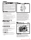
CAUTION
Disconnect power supply before making wiring connections
to prevent electrical shock and equipment damage. ALL
UNITS MUST BE WIRED STRICTLY IN ACCORDANCE
WITH WIRING DIAGRAM FURNISHED WITH UNIT.
ANY WIRING DIFFERENT FROM WIRING DIAGRAM MAY
BE HAZARDOUS TO PERSONS AND PROPERTY.
Any damage to or failure of Modine units caused by incorrect
wiring of the units is not covered by MODINE’S STANDARD
WARRANTY (see Back Cover).
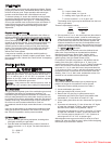
!
CAUTION
Proper air flow and distribution, across the heat exchanger
must be provided to prevent early failure of the blower unit
heater.
!
CAUTION
Do not attempt to attach ductwork of any kind to propeller
PAE models.
!
CAUTION
Check for red heat exchanger tubes. If bottom of tubes
become red while blower unit is in operation, check for
proper air volume and air distribution. Adjust blower speed or
correct discharge duct design to correct problem.
!
Heater Parts from ACF Greenhouses