


2
THE INSTALLATION AND MAINTENANCE INSTRUCTIONS IN THIS
MANUAL MUST BE FOLLOWED TO PROVIDE SAFE, EFFICIENT
AND TROUBLE-FREE OPERATION. IN ADDITION, PARTICULAR
CARE MUST BE EXERCISED REGARDING THE SPECIAL
PRECAUTIONS LISTED BELOW. FAILURE TO PROPERLY
ADDRESS THESE CRITICAL AREAS COULD RESULT IN
PROPERTY DAMAGE OR LOSS, PERSONAL INJURY, OR DEATH.
1. Disconnect power supply before making wiring connections to
prevent electrical shock and equipment damage. All units must be
wired strictly in accordance with wiring diagram furnished with the
unit.
2. Turn off all gas before installing unit heaters.
3. Gas pressure to unit heater controls must never exceed 14” W.C.
(1/2 psi).
When leak testing the gas supply piping system, the unit and its
combination gas control must be isolated during any pressure
testing in excess of 14’ W.C. (1/2 psi).
The unit should be isolated from the gas supply piping system by
closing its field installed manual shut-off valve.
4. Check gas inlet pressure at unit upstream from the combination gas
control. The inlet pressure should be 6”-7” W.C. on natural gas or
12”-14” W.C. on propane gas. Purging of gas piping should be
performed as described in ANSI Z223.1 Latest Edition, or in
Canada in CAN/CGA-B149 codes.
5. All units must be vented to the outside atmosphere.
6. Do not install in potentially explosive or flammable atmospheres
laden with grain dust, sawdust, or similar air-borne materials. In
such applications a blower type heater installed in a separate room
with ducting, including appropriate back flow prevention dampers,
to the dust-laden room is recommended.
7. Installation of units in high humidity or salt water atmospheres will
cause accelerated corrosion resulting in a reduction of the normal
life span of the units.
8. To prevent premature heat exchanger failure do not locate ANY
gas-fired unit in areas where chlorinated, halogenated or acid
vapors are present in the atmosphere.
9. Avoid installing units in extremely drafty locations. Drafts can cause
burner flames to impinge on heat exchangers which shortens life.
Maintain separation between units so discharge from one unit will
not be directed into the inlet of another.
10. Do not locate units in tightly sealed rooms or small compartments
without provision for adequate combustion air and venting.
Combustion air must have access to the confined space through a
minimum of two permanent openings in the enclosure, at least one
near the bottom. They should provide a free area of one square
inch per 1000 BTU per hour input rating of the unit with a minimum
of 100 square inches for each opening, whichever is greater.
11. Do not install unit outdoors.
12. For all sizes, minimum clearance to combustibles from the bottom
is 12 inches and from the sides 18 inches; for sizes 30-100 from the
top is 1 inch and from the vent connector 2 inches; for sizes 125-
300 from the top is 2 inches and from the vent connector 3 inches;
and for sizes 350 & 400 from the top is 3 inches and from the vent
connector 6 inches.
13. Allow at least 6” clearance at the sides and 12” clearance at rear (or
6” beyond end of motor at rear of unit, whichever is greater) to
provide ample air for combustion and proper operation of fan.
14. The minimum distance from combustible materials based on the
combustible material surface not exceeding 160°F. Clearance from
the top of the unit may be required to be greater than 6” if heat
damage, other than fire, may occur to materials above the unit
heater at the temperature described.
15. Do not install units below 7 feet measured from the bottom of the
unit to the floor.
16. Modine unit heaters are designed for use in heating applications
with ambient temperatures between 32° F and 90° F If an
application exists where ambient temperatures can be expected to
fall outside of this range, contact factory for recommendations.
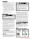
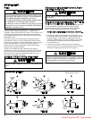
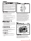
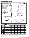
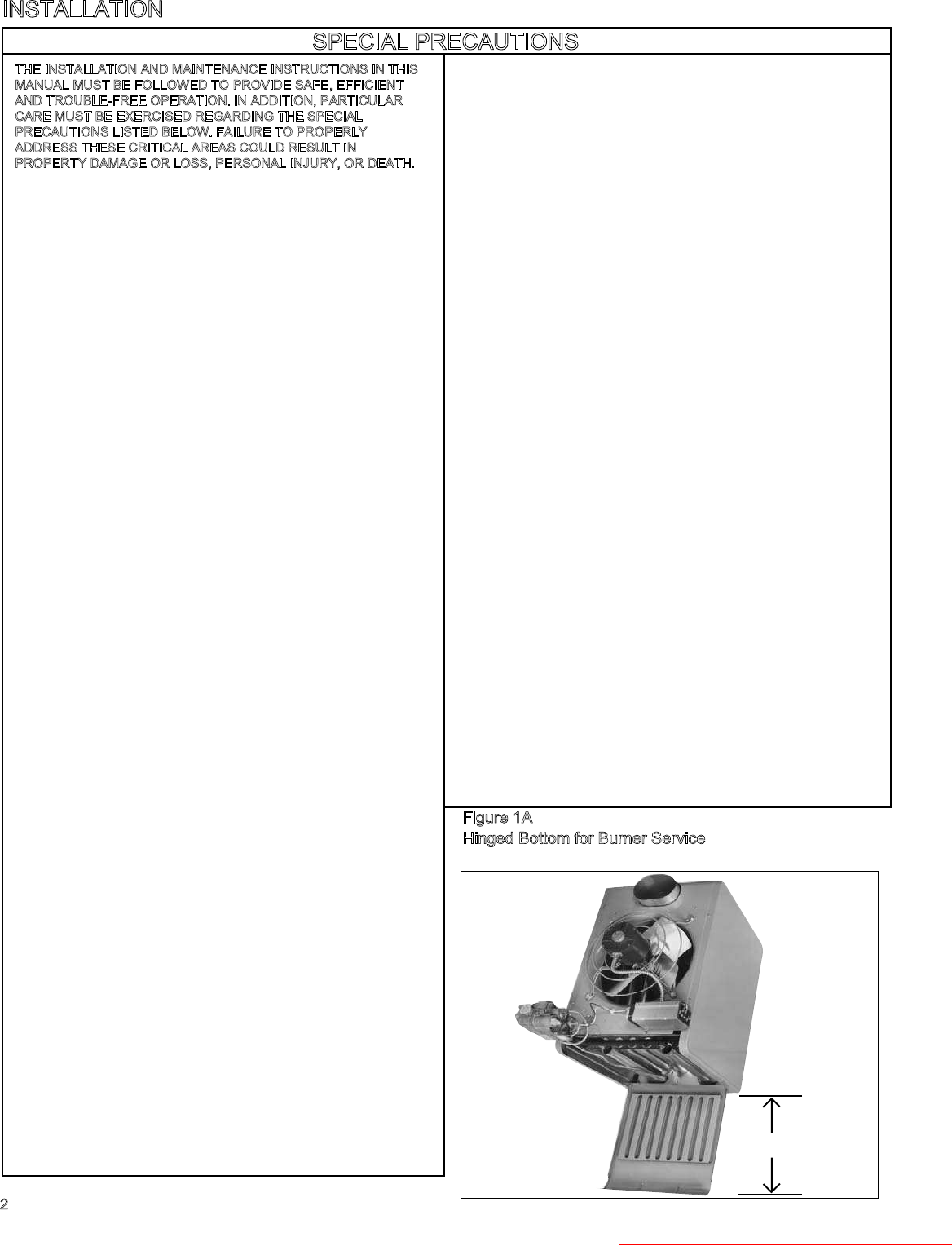
17. Provide clearance for opening hinged bottom for servicing. See
Figure 1A. Do not set unit on its bottom.
18. To assure that flames do not impinge on heat exchanger surfaces,
the unit must be suspended in a vertical and level position. Failure
to suspend unit properly may shorten the life of the unit heater.
19. Do not lift unit heater by gas controls, gas manifold, or power venter.
20.
Be sure no obstructions block air intake and discharge of unit heater.
21. Do not attach duct work, air filters, or polytubes to any propeller
(PAE) model unit heaters.
22. In aircraft hangars, keep the bottom of the unit at least 10’ from the
highest surface of the wings or engine enclosure of the highest
aircraft housed in the hangar and in accordance with the
requirements of the enforcing authority and/or NFPA No. 409 –
Latest Edition .
23. In garages or other sections of aircraft hangars such as offices and
shops which communicate with areas used for servicing or storage,
keep the bottom of the unit at least 7’ above the floor. In public
garages, the unit must be installed in accordance with the Standard
for Parking Structures NFPA #88A and the Standard for Repair
Garages NFPA #88B. In Canada, installation of unit heaters in
airplane hangars must be in accordance with the requirements of
the enforcing authority, and in public garages in accordance with
the current CAN/CGA-B149 codes.
24. Consult piping, electrical, and venting instructions in this manual
before final installation.
25. All literature shipped with your unit should be kept for future use for
servicing or service diagnosis. Do not discard any literature shipped
with your unit.
26. Gas-fired heating equipment which has been improperly vented, or
which experiences a blocked vent condition may have the flue
gases accidentally spilled into the heating space. See page 20 for
specific information about the blocked vent safety switch supplied
on the unit.
27.
When servicing or repairing this equipment, use only Modine
approved service replacement parts. A complete replacement parts
list may be obtained by contacting Modine Manufacturing Company.
Refer to the rating plate on the unit for complete unit model number,
serial number and company address. Any substitution of parts or
controls not approved by Modine will be at owners risk.
INSTALLATION
SPECIAL PRECAUTIONS
Figure 1A
Hinged Bottom for Burner Service
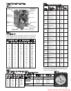
*(See Dimension "C" Table 6, page 12)
*MIN.
Heater Parts from ACF Greenhouses