


27
CONTROL OPTIONS
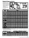
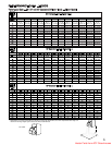
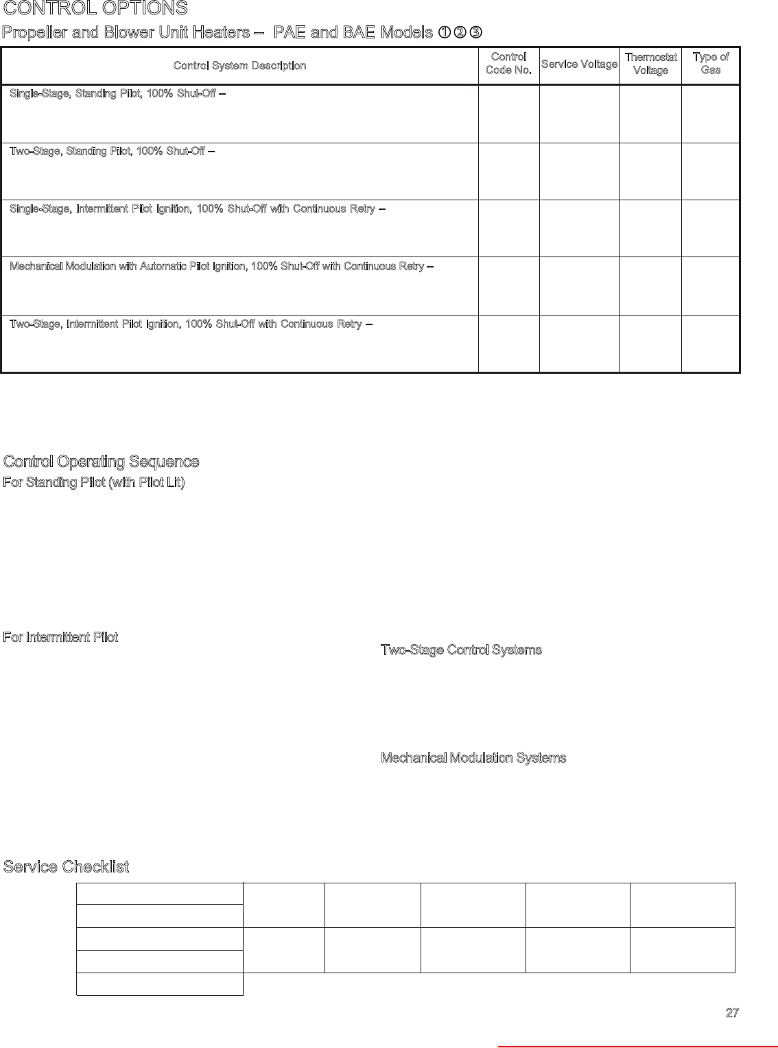
Propeller and Blower Unit Heaters – PAE and BAE Models ➀ ➁ ➂
Single-Stage, Standing Pilot, 100% Shut-Off –
Utilizes a single-stage combination gas control and
thermocouple. Pilot needs to be manually lit initially and stays lit.
Two-Stage, Standing Pilot, 100% Shut-Off –
Utilizes a two-stage gas control (which fires at 50% or
100% of full rated input) and thermocouple. Pilot needs to be manually lit initially and stays lit.
Available on PAE/BAE models only.
Single-Stage, Intermittent Pilot Ignition, 100% Shut-Off with Continuous Retry –
Utilizes a single-
stage combination gas control and an ignition control (continuous retry). Pilot is automatically lit on
call for heat.
Mechanical Modulation with Automatic Pilot Ignition, 100% Shut-Off with Continuous Retry –
Utilizes
a modulating combination gas control and an ignition control (continuous retry). Pilot is automatically
lit whenever there is power to the unit. Modulation range is between 50% and 100% fire; gas control
shuts off below 50% fire. Available on BAEmodels only.
T
wo-Stage, Intermittent Pilot Ignition, 100% Shut-Off with Continuous Retry –
Utilizes a two-stage
combination gas control (which fires at 50% or 100% of full rated input) and an ignition control
(continuous retry). Pilot is automatically lit only on call for heat. Available on PAE/BAEmodels only.
11
12
81
82
25
26
83
84
30
31
85
86
59
60
89
90
63
64
87
88
115V
200/230V
115V
200/230V
115V
200/230V
115V
200/230V
115V
200/230V
115V
200/230V
115V
200/230V
115V
200/230V
115V
200/230V
115V
200/230V
24V
24V
24V
24V
24V
24V
24V
24V
24V
24V
24V
24V
24V
24V
24V
24V
24V
24V
24V
24V
natural
natural
propane
propane
natural
natural
propane
propane
natural
natural
propane
propane
natural
natural
propane
propane
natural
natural
propane
propane
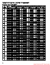
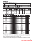
C
ontrol System Description
Control
Code No.
Service Voltage
Thermostat
Voltage
Type of
Gas
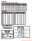
➀
Models BAE 50 thru BAE 100 with two-stage or modulating gas controls require a Category II vent system.
➁ For units with control systems having fan timer, fan starts 30 seconds (max.) after ignition and shuts down approximately 60 seconds after main burner shuts down. Available on units with up to 1 hp
motors or 14 amps @ 115V A.C. Contact factory for applications with units having motors with horsepower ratings above 1 hp or 14 amps @ 115V A.C.
➂ Whenever 230V/1φ or 230V/3φ power is used, it is necessary to specify 230V/25V controls. Whenever 460V/3φ power is used, it is necessary to specify 230V/25V controls and in addition, a
460V/230V/75VA step-down transformer (by others) is required (if the power exhauster accessory is used, the step-down transformer by others needs to be 250VA). On 230V or 460V/3φ systems,
the motor starter coil voltage (motor starter by others) must be 230V. For 200V/3φ systems, the motor starter coil voltage (motor starter by others) must be 200V.
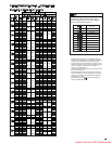
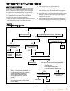
C
ontrol Operating Sequence
For Standing Pilot (with Pilot Lit)
Upon a call for heat from thermostat, power is supplied to the
combination gas control and at the same time power is supplied to
the fan timer. The main burner should light immediately. The fan
motor will start in 15 to 45 seconds.
When the thermostat has been satisfied, power is turned off to the
combination gas control and fan timer. The main burner will go out
but the pilot will continue to burn. The fan motor will continue to
operate for 45 to 75 seconds to allow the heat exchanger to cool
down.
F
or Intermittent Pilot
Upon a call for heat from the thermostat, power is supplied to the
ignition control and at the same time power is supplied to the fan
timer. Sparking will start at the pilot immediately and at the same
time the first operator of the combination gas control opens to allow
gas to flow to the pilot burner. The pilot flame should light and be
sensed (proven) in a few seconds. As soon as the pilot flame is
sensed the sparking will stop and the second operator of the
combination gas control will open allowing gas to flow to the main
burner. In 15 to 45 seconds from the time the thermostat called for
heat the fan motor will start.
On systems utilizing control codes 08 and 09, the ignition control will
attempt to light the pilot once the system is turned on. If the pilot is
not sensed for any reason, the spark will continue indefinitely until
the pilot flame is sensed or until power is interrupted to the system.
On systems utilizing control codes 30, 31, 85 or 86 the sequence is
similar, except that the system will attempt to light the pilot for 70
seconds once there is a demand for heat. If the pilot is not sensed
for any reason, the ignition control will wait for a predetermined time
with the combination gas control closed and no spark. After the
predetermined time lapses, the cycle will begin again. The time that
lapses between cycles is at pre-programmed intervals
(approximately 6 minutes). This will continue indefinitely until the pilot
flame is sensed or until power is interrupted to the system.
When the thermostat has been satisfied, power is turned off to the
ignition control and the combination gas control, so both the main
gas and pilot gas are turned off. The fan will continue to operate for
45 to 75 seconds to allow the heat exchanger to cool down.
T
wo-Stage Control Systems
The thermostat will start the unit with the combination gas control in
the first stage (50% of normal input). If the thermostat senses a
further drop in temperature the second stage (100% of normal input)
of the combination gas control will be energized. When the
thermostat senses an increase in temperature the combination gas
control will be returned to the first stage operation.
M
echanical Modulation Systems
When power is turned on the pilot is automatically lit. When the
sensing bulb attached to the combination gas control senses a drop
in temperature the valve will open at 50% of normal input. If the
temperature drops further the valve will open further. As the
temperature rises the valve will return to 50% of normal input. If the
temperature rises further the valve will close.
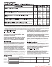
Service Checklist
Date Intalled Serviced by &
Serial No. Date Serviced
Model No. Serviced by &
Power Code Date Serviced
Control Code
Heater Parts from ACF Greenhouses