


4
INSTALLATION
NOTE:
A
v
ent
is the vertical passageway used to convey flue gases from the
unit or the vent connector to the outside atmosphere. A
v
ent connector
is
the pipe which connects the unit to a vent or chimney.
V
enting Instructions
1. Using Table 1, determine the venting system category of the unit to be
installed.
2. Using Table 2, determine the venting requirements for the category
determined above. The installation of a Category II unit must conform to
these requirements (detailed in following sections) in addition to those
listed below.
3.
Select size of vent pipe to fit vent pipe connection at rear of appliance (see
Page 12, Dimension J). (Exception: All PAE/BAE 50 models with two-stage
or modulating controls must use a 5 inch vent.) Do not use a vent pipe
smaller than the vent pipe connection on the unit. Vent pipe should be
galvanized steel or other suitable corrosion-resistant material. Follow the
National Fuel Gas Code for minimum thicknesses of vent material; minimum
thicknesses for vent connectors vary depending on pipe diameter.
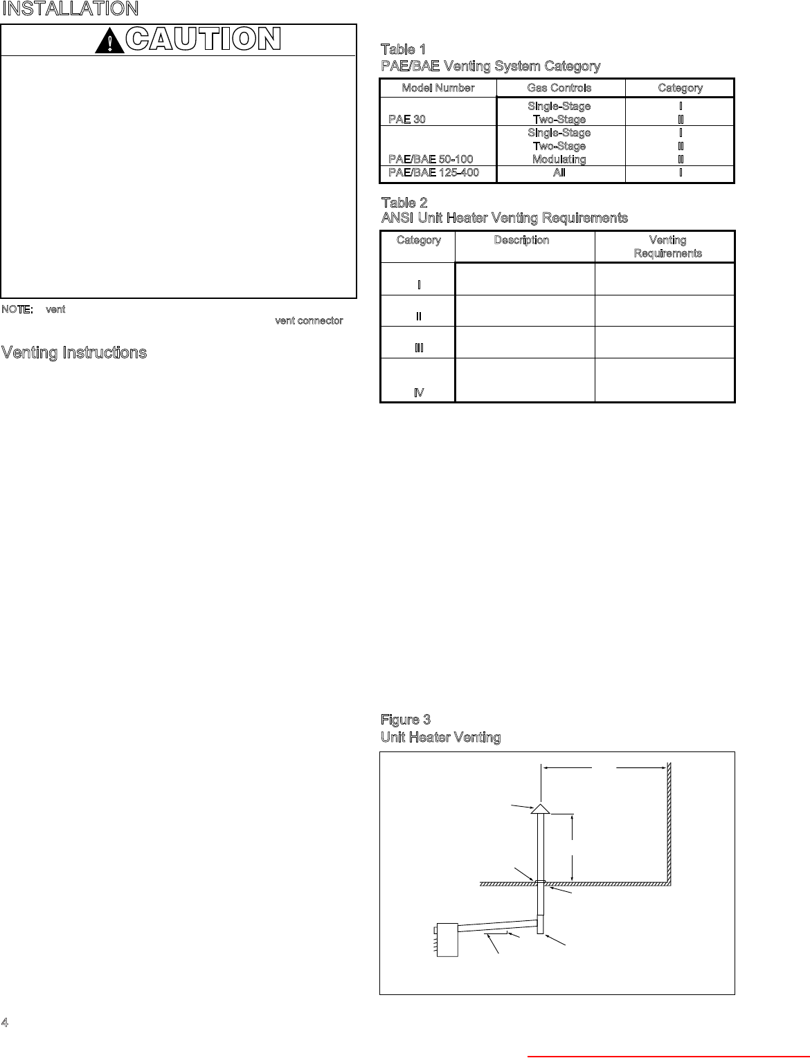
4. Limit length of horizontal runs to 75% of vertical height. Install with a
minimum upward slope from unit of 1/4 inch per foot and suspend
securely from overhead structure at points no greater than 3 feet apart.
For best venting, put as much vertical vent as close to the unit as
possible. Fasten individual lengths of vent together with at least three
corrosion-resistant sheet-metal screws.
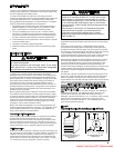
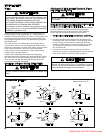
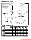
5. Avoid venting through unheated space when possible. When venting
does pass through an unheated space, Modine recommends the use of
Type B double wall vent. If single wall vent is used, insulate vent runs
greater than 5 feet to minimize condensation. Use insulation that is
noncombustible with a rating of not less than 350°F. Install a tee fitting at
the low point of the vent system to provide a drip leg with a clean out cap
as shown in Figure 3. The drip leg should be cleaned annually.
6. Keep single wall vent pipe at least 6 inches from combustible material
(see page 2, section 12 for allowable reductions). For double wall vent
pipe, maintain clearances listed on vent pipe (Category I and II units).
The minimum distance from combustible material is based on the
combustible material surface not exceeding 160°F. Clearance from the
vent connector, vent, or top of unit may be required to be greater than
the minimum clearance if heat damage other than fire (such as material
distortion or discoloration) may occur.
7. Where the vent passes through a combustible floor or roof, a metal
thimble 4 inches greater than the vent diameter is necessary. If there is 6
feet or more of vent pipe in the open space between the unit and where
the vent pipe passes through the floor or roof, the thimble need only be 2
inches greater than the diameter of the vent pipe. If a thimble is not
used, all combustible material must be cut away to provide the specified
clearance to combustibles. Any material used to close the opening must
be noncombustible.
8.
Top of vertical vent should extend at least two feet above the highest
point where it passes through a roof and at least 2 feet higher than any
portion of a building within a horizontal distance of 10 feet (see Figure 3).
9. Use a vent terminal to reduce downdrafts and moisture in vent. A vent
terminal that is very open will avoid spillage at unit’s diverter relief
opening and tripping of the blocked vent safety switch.
10.
Check vent system to see that combustion products are being vented
properly. Operate unit for several minutes and then pass a lighted match
around the edge of the diverter relief opening. If the flame is drawn into
the opening, the vent system is drawing properly. If not, make
adjustments to provide adequate draft (see page 21).
ADDITIONAL VENTING REQUIREMENTS FOR CATEGORY II UNITS
Vent system must provide for drainage of condensate. At the low point of the
vent system, install a tee fitting with a connector and attach flexible tubing,
minimum 3/8 inch I.D., and run to a drain.
ADDITIONAL VENTING REQUIREMENTS FOR VENTING INTO AN
EXISTING MASONRY CHIMNEY OR COMMON VENT (CATEGORY I and II
UNITS ONLY)
1. Do not vent a Category I or II unit into a common vent with mechanical
draft systems operating under positive pressure (Category III or IV units).
2. When connecting vent to an existing chimney, do not push vent pipe
beyond internal surface of chimney.
3. When venting into a common vent, the area of the common vent should
be equal to or greater than the area of the largest vent plus 50 percent of
the area of all additional vents.
4. When venting into a common vent, the individual vents should enter at
different levels
10' MIN.
TO WALL OR ADJOINING BUILDING
2'
MIN.
ROOF FLASHING
USE THIMBLE
THROUGH CEILING
APPROVED
TERMINAL
1'0"
SLOPE 1/4" TO
THE FOOT
UNIT
1/4"
DRIP LEG WITH
CLEANOUT CAP
*SIZE ACCORDING TO EXPECTED SNOW DEPTH.
*
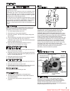
Figure 3
Unit Heater Venting
CAUTION
Gas Unit Heaters must be vented – do not operate
unvented.
A built-in draft hood (diverter) is provided – additional
external draft hoods (diverters) are not required or
permitted.
Gas-fired heating equipment that has been improperly
vented or which experiences a blocked vent condition may
have flue gases accidentally spilled into the heated space.
See page 20 for specific information about the blocked vent
safety switch supplied on the unit.
Installation must conform with local building codes or in the
absence of local codes, with Part 7, Venting of Equipment,
of the National Fuel Gas Code, ANSI Z223.1 (NFPA 54) -
Latest Edition. In Canada installation must be in accordance
with CAN/CGA-B149.1 for natural gas units, and CAN/CGA-
B149.2 for propane units.
!
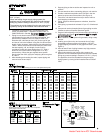
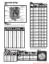
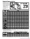
Model Number Gas Controls Category
Single-Stage I
PAE 30 Two-Stage II
Single-Stage I
Two-Stage II
PAE/BAE 50-100 Modulating II
PAE/BAE 125-400 All I
Table 1
PAE/BAE Venting System Category
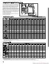
Category Description Venting
Requirements
Negative vent pressure Follow standard
I
Non-condensing venting requirements.
Negative vent pressure Condensate must be
II
Condensing drained.
Positive vent pressure Vent must be gastight.
III
Non-condensing
Positive vent pressure Vent must be liquid and
Condensing gastight. Condensate
IV
must be drained.
Table 2
ANSI Unit Heater Venting Requirements
Heater Parts from ACF Greenhouses