


5
Piping
1. Installation of piping must be in accordance with local
codes, and ANSI Z223.1, “National Fuel Gas Code,” or
CAN/CGA-B149 in Canada.
D
o not use flexible connectors
.
2. Piping to units should conform with local and national
requirements for type and volume and gas handled, and
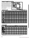
pressure drop allowed in the line. Refer to Table 4, to
determine the cubic feet per hour (cfh) for the type of gas
and size of unit to be installed. Using this cfh value and the
length of pipe necessary, determine the pipe diameter from
Table 1. Where several units are served by the same main,
the total capacity, cfh, and length of main must be
considered. Avoid pipe sizes smaller than 1/2”. Table 1
allows for the usual number of fittings with a 0.3” W.C.
pressure drop. Where the gas supplied has a specific
gravity other than 0.60, apply the multiplying factor as given
in Table 2.
3. After threading and reaming the ends, inspect piping and
remove loose dirt and chips.
4. Support piping so that no strains are imposed on unit or
controls.
5. Use two wrenches when connecting piping to unit controls.
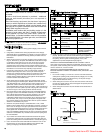
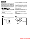
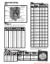
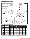
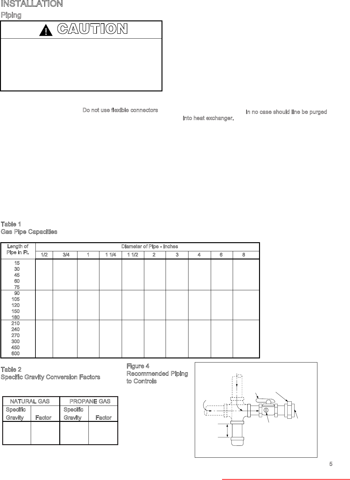
6. Provide a sediment trap before each unit and in the line
where low spots cannot be avoided. (See Figure 4).
7. Take-off to unit should come from top or side of main to
avoid trapping condensate.
8.
Piping, subject to wide temperature variations, should be
insulated.
9. Pitch piping up toward unit at least 1/4” per 15’ of horizontal
run.
10. Compounds used on threaded joints of gas piping must be
resistant to action of liquefied petroleum gases.
11. Purge air before lighting unit by disconnecting pilot tubing at
combination gas control.
I
n no case should line be purged
into heat exchanger.
12. After installation, check system for gas leaks, using a soap
solution.
13. Install a ground joint union and a manual shut off valve
immediately upstream of the unit including a 1/8” NPT
plugged tapping accessible for test gage connection. (See
Figure 4).
14. Allow at least 5 feet of piping between any high pressure
regulator and unit control string.
15. When leak testing the gas supply piping system, the
appliance and its combination gas control must be isolated
during any pressure testing in excess of 14” W.C. (1/2 psi)
The appliance should be isolated from the gas supply
piping system by closing its field installed manual shutoff
valve.
GAS
SUPPLY LINE
GAS
SUPPLY LINE
GROUND
JOINT
UNION
MANUAL
SHUT-OFF
VALVE
3"
MIN.
SEDIMENT
TRAP
PLUGGED
1/8" NPT TEST
GAGE CONNECTION
TO
CONTROLS
CAUTION
Gas pressure to unit heater controls must never exceed 14"
W.C. (1/2 psi).
When leak testing the gas supply piping system, the
appliance and its combination gas control must be isolated
during any pressure testing in excess of 14" W.C. (1/2 psi).
The appliance should be isolated from the gas supply piping
system by closing its field installed manual shut-off valve.
!
INSTALLATION
Figure 4
Recommended Piping
to Controls
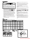
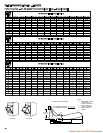
Table 2
Specific Gravity Conversion Factors
Multiplying factors to be sued with table 1 when the specific
gravity of gas is other than 0.60.
Table 1
Gas Pipe Capacities
In Cu. Ft. per Hour with Pressure Drop pf 0.3 in. W.C. with Specific Gravity 0.60.
NATURAL GAS
Specific
Gravity Factor
0.55 1.04
0.60 1.00
0.65 0.962
P
ROPANE GAS
Specific
Gravity Factor
1.50 0.633
1.53 0.626
1.60 0.612
1/2 3/4 1 1 1/4 1 1/2 2 3 4 6 8
15
76 218 440 750 1220 2480 6500 13880 38700 79000
3
0
73 152 285 590 890 1650 4700 9700 27370 55850
45
44 124 260 435 700 1475 3900 7900 23350 45600
60
50 105 190 400 610 1150 3250 6800 19330 39500
75
97 200 345 545 1120 3000 6000 17310 35300
9
0
88 160 320 490 930 2600 5400 15800 32250
1
05
80 168 285 450 920 2450 5100 14620 29850
120
158 270 420 860 2300 4800 13680 27920
150
120 242 380 710 2000 4100 12240 25000
180
128 225 350 720 1950 4000 11160 22800
210
205 320 660 1780 3700 10330 21100
2
40
190 300 620 1680 3490 9600 19740
270
178 285 580 1580 3250 9000 18610
3
00
170 270 545 1490 3000 8500 17660
4
50
140 226 450 1230 2500 7000 14420
6
00
119 192 380 1030 2130 6000 12480
Diameter of Pipe - Inches
Length of
Pipe in Ft.
Heater Parts from ACF Greenhouses