


29
ENGLISH
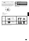
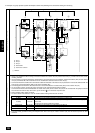
A B C
E
D
M1 M2
M1 M2 S
TB7
TB3
IC
(51)
M1 M2 S
TB5
RC
(01)
IC
M1 M2 S
TB5
(02)
IC
M1 M2 S
TB5
(04)
IC
M1 M2 S
TB5
(03)
IC
M1 M2 S
TB5
(05)
IC
M1 M2 S
TB5
(07)
IC
M1 M2 S
TB5
(06)
TB6
(101)
RC
TB6
(105)
RC
TB6
(103)
RC
TB6
(155)
CN40
OC
M1 M2
SM1 M2
TB7
TB3
(52)
OC
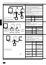
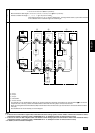
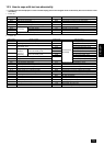
Permissible Lengths
Prohibited Items
• Max length via outdoor units: L1+L2+L3+L4+L5+L6+L7+L9,
L
1+L2+L3+L4+L5+L6+L8+L9
=
500 m (1.25 mm
2
)
• Max transmission cable length: L1+L2+L3+L4, L5+L6+L7, L5+L6+L8, L7+L8
=
200 m (1.25 mm
2
)
• Remote controller wire length: r
1, r2, r3, r4
=
10 m (0.5 to 0.75 mm
2
)
If the length exceeds 10 m, use a 1.25 mm
2
shielded wire. The length of this section (L8) should be included
in the calculation of the maximum length and overall length.
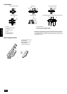
A Group 1
B Group 3
C Group 5
D Shielded Wire
E Remote Controller
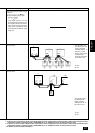
• The terminal S on the terminal block (TB7) for the central control panel should be connected to the ground terminal of the electric
components box of the only outdoor unit installed with the CN40 into which the jumper connector was inserted.
• Never connect together the terminal blocks (TB5) for transmission wires for indoor units (IC) that have been connected to different outdoor
units (OC).
• Set all addresses to ensure that they are not overlapped.
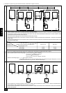
Note:
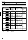
1. If there is one or more 200 or higher indoor units within the same cooling system, and the number of indoor units exceeds 16 units, a
transmission booster is necessary (when a “PAR-F25MA Ver. F” or subsequent version of remote control is used).
2. If there is not even one 200 or higher indoor unit within the same cooling system, and the number of indoor units exceeds 20 units, a
transmission booster is necessary (when a “PAR-F25MA Ver. F” or subsequent version of remote control is used).
* For details, see wire connection example C.