


25
ENGLISH
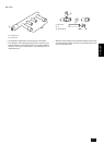
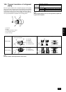
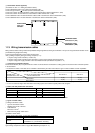
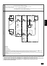
4 Transmission booster (optional)
(For details, see item 11.3. “Wiring transmission cables”)
Connect 220/230/240 VAC to L/N of power terminal block (TB1).
Connect the ground to the terminal of power terminal block (TB1).
Connect the outdoor unit side transmission cables to A/B of transmission cables terminal block 1 (TB2).
Connect the outdoor unit side shield to S of transmission cables terminal block 1 (TB2).
Connect additional indoor unit side transmission cables to A/B of transmission cables terminal block 2 (TB3).
Connect additional indoor unit side shield to S of transmission cables terminal block 2 (TB3).
OC
IC
RC
RP
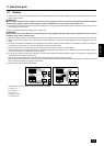
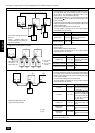
Remote controller PAR-F 25MA
Prior to Ver. E After Ver. F
16 (32) 20 (40)
16 (32) 16 (32)
200 or lower
200 or higher
(*1)
Capability of the
connected indoor units
Remote controller type
Number of connected indoor units that can be
connected without a RP.
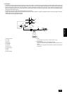
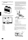
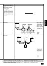
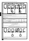
Name Code Possible unit connections
Outdoor unit
Indoor unit
Remote controller
Other
Outdoor unit controller
Indoor unit controller
Remote controller (*1)
Transmission booster unit
–
2 to 32 units per 1 OC (*1)
2 units maximum per group
0 to 1 unit per 1 OC (*1)
11.3. Wiring transmission cables
Wiring method, address setting method and permissible wiring length differ according to and whether or not you are using transmission booster. Check
permissible wiring length before wiring.
A may be required depending on the number of indoor units.
Item 4 “Wiring examples” gives typical wiring examples (A – C).
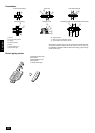
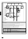
A. System using remote controller (1 outdoor unit)
B. System using remote controller (system operated as a group among multiple refrigerant systems)
C. System using power supply extension unit for transmission booster (combination of systems a – b)
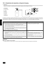
1 Connecting a transmission booster
A transmission booster (RP) is required when the number of connected indoor unit models in a cooling system exceeds the number of models specified
in the chart below.
* The maximum number of units that can be controlled is determined by the indoor unit model, the type of remote controller and their capabilities.
The number of indoor units and the total number of remote controllers is displayed within the parenthesis ( ).
*1 If even one unit that is higher than 200 exists in the cooling system, the maximum capacity will be “200 or higher”.
2 Name, code and possible unit connections
*1 A transmission booster (RP) may be required depending on the number of connected indoor unit controllers.
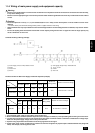
3 Types of control cables
(1) Wiring transmission cables
• Types of transmission cables
Shielding wire CVVS or CPEVS
• Cable diameter
More than 1.25 mm
2
• Maximum wiring length within 200 m
(2) Remote control cables
Kind of remote control cable 2-core cable (unshielded)
Cable diameter 0.5 to 0.75 mm
2
Remarks
When 10 m is exceeded, use cable with the same
specifications as (1) Transmission line wiring.
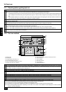
4 Wiring examples
Typical wiring examples are shown on pages
26
to
30
(Wiring examples A – C).
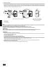
PAC-SF46EPA
TRANSMISSION BOOSTER
3.4kg
220-240V:0.7A ~/N
WEIGHT
POWER RATING
MODEL
MADE IN JAPAN
50
UP
Transmission cables
Transmission cables
terminal block 2 (TB3)
terminal block 2 (TB3)
Transmission cables
Transmission cables
terminal block 1 (TB2)
terminal block 1 (TB2)
Power terminal
Power terminal
block (TB1)
block (TB1)
and Earth
and Earth
Power terminal
block (TB1)
and Earth
Transmission cables
terminal block 2 (TB3)
Transmission cables
terminal block 1 (TB2)