


28
ENGLISH
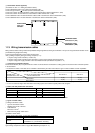
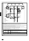
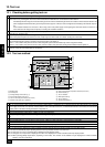
h. The group setting operations among the multiple indoor units is done by the remote controller (RC) after the electrical power has been
turned on.
A B C
E
D
M1 M2
M1 M2 S
TB7
TB3
IC
(51)
M1 M2 S
TB5
RC
(01)
IC
M1 M2 S
TB5
(02)
IC
M1 M2 S
TB5
(04)
IC
M1 M2 S
TB5
(03)
IC
M1 M2 S
TB5
(05)
IC
M1 M2 S
TB5
(07)
IC
M1 M2 S
TB5
(06)
L1
L8
r1
r4
L9
L2 L3 L4
L5 L6 L7
TB6
(101)
RC
TB6
(105)
RC
TB6
(103)
RC
TB6
(155)
CN40
OC
M1 M2
M1 M2 S
TB7
TB3
(52)
OC
r2
r3
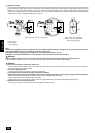
Example of transmission line wiring
A Group 1
B Group 3
C Group 5
D Shielded Wire
E Sub Remote Controller
( ) Address
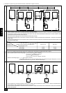
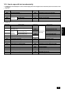
Wiring method, address setting method
Unit Range Setting Method
IC (Main) 01 to 50 Use the most recent address within the same group of indoor units
IC (Sub) 01 to 50
Use an address, other than that of the IC (Main) from among the units within the same group of
indoor units
This must be in sequence with the IC (Main)
Outdoor Unit 51 to 100 Use the most recent address of all the indoor units plus 50
Main Remote Controller 101 to 150 Set at an IC (Main) address within the same group plus 100
Sub Remote Controller 151 to 200 Set at an IC (Main) address within the same group plus 150
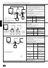
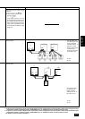
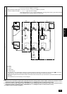
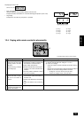
B. Example of a group operation system with multiple outdoor units (Shielding wires and address setting are necessary)
a. Always use shielded wire when making connections between the outdoor unit (OC) and the indoor unit (IC), as well for all OC-OC, and IC-
IC wiring intervals.
b. Use feed wiring to connect terminals M1 and M2 and the ground terminal on the transmission cable terminal block (TB3) of each outdoor
unit (OC) to terminals M1, M2 and terminal S on the transmission cable block of the indoor unit (IC).
c. Connect terminals M1 and M2 on the transmission cable terminal block of the indoor unit (IC) that has the most recent address within the
same group to the terminal block (TB6) on the remote controller (RC).
d. Connect together terminals M1, M2 and terminal S on the terminal block for central control (TB7) for the outdoor unit (OC).
e. On one outdoor unit only, change the jumper connector on the control panel from CN41 to CN40.
f. Connect the terminal S on the terminal block for central control (TB7) for the outdoor unit (OC) for the unit into which the jumper connector
was inserted into CN40 in Step above to the ground terminal
in the electrical component box.
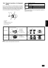
g. Set the address setting switch as follows.
* To set the outdoor unit address to 100, the outdoor address setting switch must be set to 50.