11 - 32
MELSEC-F
TROUBLESHOOTING11
11 - 32
11.5 Troubleshooting Flowchart
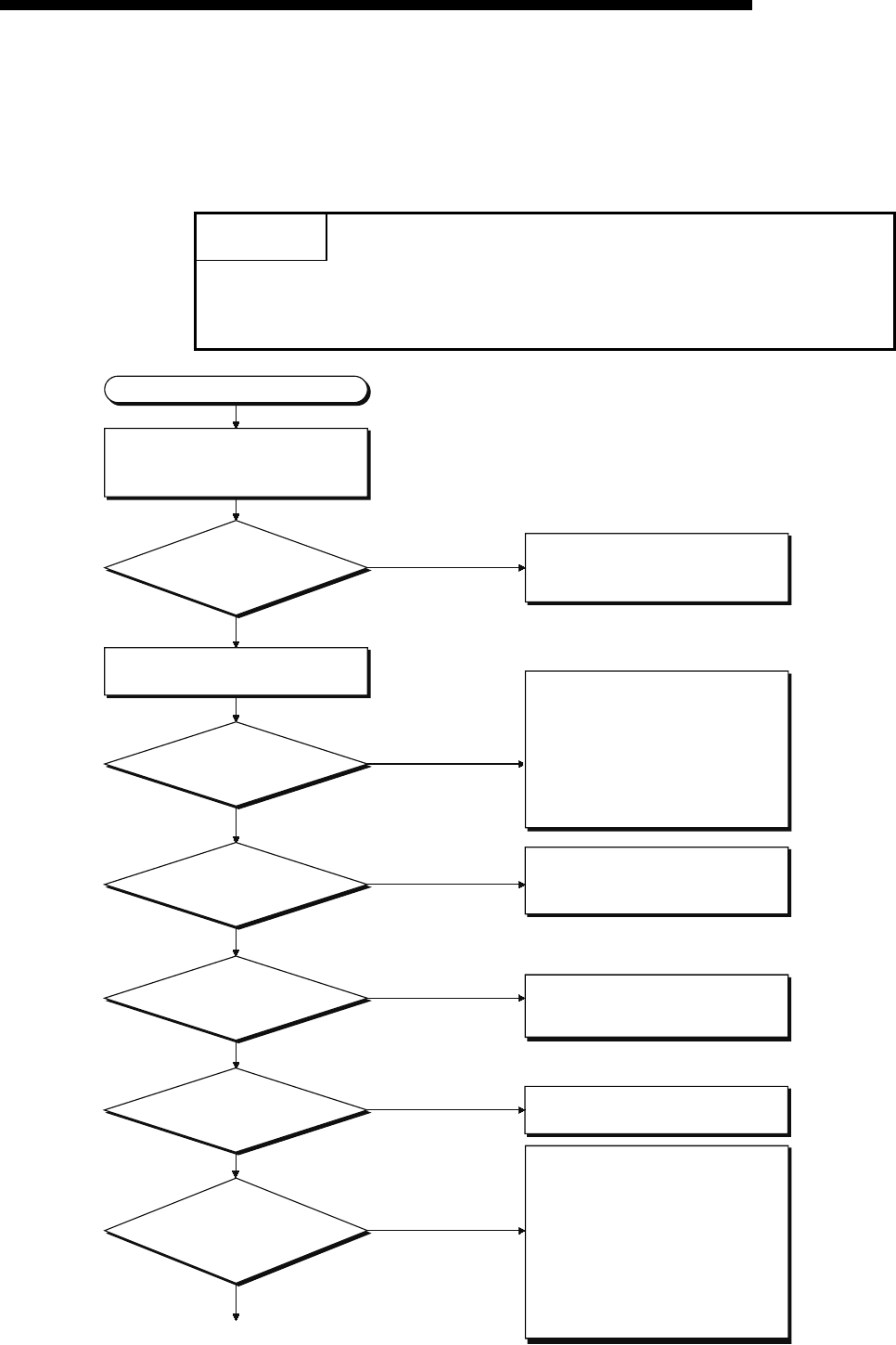
This section explains some simple troubleshooting procedures when the Ethernet
module and an external device have communication problems in a flowchart format.
(*1)
POINT
If trouble occurs when using the Ethernet module, check the block status, error
status and others for the Ethernet module using the Ethernet diagnostic function of
FX Configurator-EN-L described in Subsection 11.2.2.
Data cannot be communicated.
Check whether or not an error
occurred in the PLC base unit to
which the Ethernet module is installed.
Did an error
that makes the PLC
stop processing
occur?
Check the status of the applicable
Ethernet module.
Refer to the troubleshooting section
in the applicable PLC ’s user’s
manual and fix the problems.
YES
NO
Is the Ethernet module’s
[RUN] LED on?
NO
YES
Is the connection cable
securely connected?
NO
Lock the cable securely.
Is the Ethernet module’s
[ERR.] LED on?
Check whether or not a parameter
error occurred. If an error is found,
first correct it and then re-download.
NO
Is the Ethernet module’s
[COM.ERR.] LED on?
NO
Check the error contents using the
diagnostics function of
FX Configurator-EN-L.
Is the data code
(binary/ASCII) setting of the
communication data
correct?
NO
YES
Data cannot be sent/received
because the data code is different in
sending node and receiving node
and the command can therefore not
be successfully decoded.
Change the setting in
[Communicational data code] of
[Operational settings] using
FX Configurator-EN-L.
(See Section 4.6.) (*2)
1)
Turn on the PLC and Ethernet module
again.
If the [RUN] LED does not turn on
even after resetting, the Ethernet
module’s hardware may be faulty.
Replace the Ethernet module and
restart all the external devices that
communicate with the local station.


