


9 - 1
WHEN COMMUNICATING DATA USING THE MC PROTOCOL9
9 - 1
9
MELSEC-F
9 WHEN COMMUNICATING DATA USING THE MC PROTOCOL
This chapter explains the message format, how to designate data items in a message
and restrictions for data communication with an Ethernet module using MC protocol
with A compatible 1E frames.
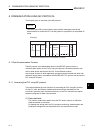
9.1 Message Formats and Control Procedures
This section explains the message format and control procedure for each command
when data communication is performed using A compatible 1E frames.
The MC protocol for the Ethernet module is a subset of A compatible 1E frames.
Both TCP/IP and UDP can be used as lower layer protocol and support both ASCII
code and binary code.
9.1.1 How to read the command reference section
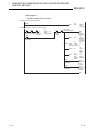
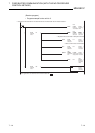
The following explains how to read the message explanation diagrams shown in each
of the command description Sections 9.3 through 9.5.
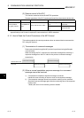
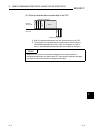
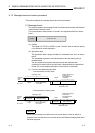
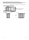
(1) When an external device reads data from the PLC
1) Area A indicates transmission from the external device to the PLC.
2) Area B indicates transmission from the PLC to the external device.
3) The program of the external device is generated so that the data is
transmitted sequentially from left to right. (For example: in case of
area A, data should be sequentially sent from Header to the right.)
(Command message)
External
device side
Header
Subheader
PC No.
Monitoring
timer
PLC side
Header
Subheader
Complete code
Area B
(Response message)
Area A