9 - 19
MELSEC-F
WHEN COMMUNICATING DATA USING THE MC PROTOCOL9
9 - 19
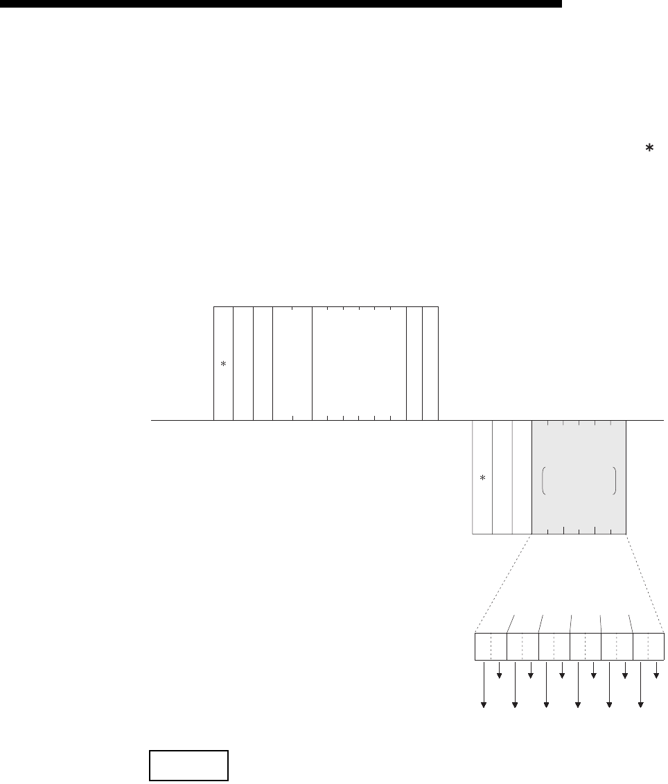
9.3.2 Batch read in bit units (command: 00)
The examples shown in this section explain the command/response format when
batch-reading the bit device memory.
For more details on the order and contents of data items of the areas marked by " "
shown in the control procedure diagram, see Subsection 9.1.2.
[Control procedure]
Reading the on/off status of M100 to M111 of the PLC on which the FX3U-ENET-L is
loaded.
(1) Communication in binary code
NOTE
Use the designation "00H" when the number of device points is 256 points.
0A
H
64
H
00
H
Subheader
PC No.
Number of device points
Head device
(Data name)
External device
side
(Example)
(Data name)
PLC side
(Example)
00
H
FF
H
00
H
00
H
00
H
20
H
4D
H
0C
H
00
H
80H
Subheader
Complete code
00
H
10
H
10
H
10
H
10
H
10
H
10
H
Data for the number
of designed device
points
Characters for the
number of device
points
0
1
0
1
0
1
0
1
0
1
0
1
Status
of M100
Status
of M101
Status
of M102
Status
of M103
Status
of M104
Status
of M105
Status
of M106
Status
of M107
Status
of M108
Status
of M109
Status
of M110
Status
of M111
Monitoring
timer
HL L--- -H


