


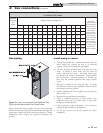

Water flow switch
A water flow switch is factory installed in the outlet piping on
all heating boilers and water heaters. The flow switch must
prove water flow before a trial for ignition can begin. The flow
switch requires a minimum flow of 26 GPM to make the flow
switch and start burner operation. A water flow switch meets
most code requirements for a low water cutoff device on
boilers requiring forced circulation for operation. A fault
message, Flow Sw/LWCO will be indicated in the Operator
Interface on a low water flow condition as sensed by the flow
switch.
Low water cutoff
If this boiler is installed above radiation level, a low water
cutoff device must be installed at the time of boiler
installation. An electronic low water cutoff is available as a
factory supplied option on all models. The low water cutoff
should be inspected every 6 months. A fault message, Flow
Sw/LWCO will be indicated in the Operator Interface on a low
water condition as sensed by the low water cutoff.
Relief valve
This unit is supplied with a relief valve(s) sized in accordance
with ASME Boiler and Pressure Vessel Code, Section IV
(“Heating Boilers”). The relief valve(s) is installed in the
vertical position and mounted in the hot water outlet. No
valve is to be placed between the relief valve and the unit. To
prevent water damage, the discharge from the relief valve shall
be piped to a suitable floor drain for disposal when relief
occurs. No reducing couplings or other restrictions shall be
installed in the discharge line. The discharge line shall allow
complete drainage of the valve and line. Relief valves should be
manually operated at least once a year.
ƽ CAUTION
Avoid contact with hot discharge water.
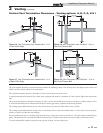
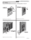
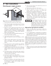
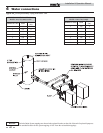
Heating boiler installations
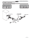
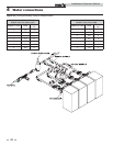
Piping of the boiler system
The drawings in this section show typical boiler piping
installations, see FIG.’s 4-3 through 4-6. Before beginning the
installation, consult local codes for specific plumbing
requirements. The installation should provide unions and
valves at the inlet and outlet of the boiler so it can be isolated
for service. An air separation device must be supplied in the
installation piping to eliminate trapped air in the system.
Locate a system air vent at the highest point in the system. The
system must also have a properly sized expansion tank
installed. Typically, an air charged diaphragm-type expansion
tank is used. The expansion tank must be installed close to the
boiler and on the suction side of the system pump to ensure
proper operation.
ƽ CAUTION
The boiler system should not be operated at
less than 12 PSIG.
Hot water piping must be supported by suitable hangers or floor
stands, NOT by the boiler. Copper pipe systems will be subject
to considerable expansion and contraction. Rigid pipe hangers
could allow the pipe to slide in the hanger resulting in noise
transmitted into the system. Padding is recommended on rigid
hangers installed with a copper system. The boiler pressure
relief valve must be piped to a suitable floor drain. See the Relief
Valve section on this page.
ƽ CAUTION
A leak in a boiler “system” will cause the
“system” to intake fresh water constantly,
which will cause the tubes to accumulate a
lime/scale build up. This will cause a non-
warrantable failure.
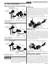
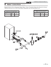
Water connections (heating boilers only)
All boilers have 2 1/2 inch copper pipe inlet and outlet
connections. Installed piping to and from the boiler must be a
minimum of 2 1/2 inch diameter.
ƽ CAUTION
Field installed reducing bushings must not
be used.
Any reduction in pipe size may decrease flow resulting in high
water temperatures, boiler noise, flashing to steam, and non-
warrantable heat exchanger damage.
The boiler may be installed with either a primary/secondary
piping system or with full system flow provided to the boiler. It
is important to guarantee that adequate flow is provided to
properly dissipate heat from the boiler and also ensure that flow
through the boiler does not exceed the maximum recommended
flow rate of 75 GPM for Models 502 - 1302 and 90 GPM for
Models 1501 - 2001 for a boiler equipped with a copper heat
exchanger.
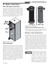
Boiler circulator requirements
This is a low mass, high efficiency hot water boiler which must
have adequate flow for quiet, efficient operation. Pump
selection is critical to achieve proper operation. A pump should
be selected to achieve proper system design water temperature
rise. A system pump may provide full flow through the boiler or
a separate pump may be installed in a secondary loop to the
boiler. Pipe diameter and length are critical to ensure proper
flow through the boiler. A System Temperature Rise Chart
(Table 4B on page 42) is provided to assist in proper pump
selection. This table provides GPM and boiler head-loss at
various temperature rises for each model based on Btu/hr input.
Temperature rise is the difference in boiler inlet temperature and
boiler outlet temperature while the boiler is firing at full rate.
Example: The boiler inlet temperature is 160°F (71.1°C) and the
boiler outlet temperature is 180°F (82.2°C). This means that
there is a 20°F (11.1°C) temperature rise across the boiler. The
boiler temperature rise is visible in the Operator Interface on the
boiler’s front control panel.
35
4 Water connections (continued)
Installation & Operation Manual