Installation & Operation Manual
20
2 Venting
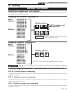
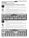
Non-Condensing vent options: CAT I
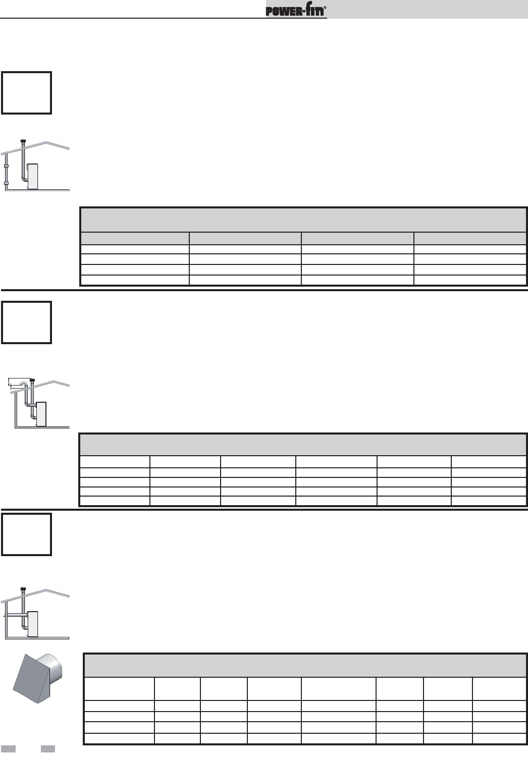
Vertical negative draft venting system - see page 19.
Units that may be vented with a Category I, Type “B” vent material operate with limited burner modulation.
These units can be identified by the Category I and the control number F9 or B9 as noted on the unit’s rating
plate. These are the only units that can be vented with standard double-wall vent material. See the General
Venting and the Negative Draft General Venting on pages 21 and 22. The flue must terminate at the rooftop and
follow the clearance requirements on pages 27 and 28. Combustion air is supplied from the equipment room.
The installation of the vent must conform to the latest edition of the National Fuel Gas Code, ANSI Z223.1, in
Canada, the latest edition of CGA Standard B149 Installation Code for Gas Burning Appliances and Equipment.
The negative draft in a conventional vent installation must be within the range of 0.02 to 0.08 inches w.c. to
ensure proper operation. Make all draft readings while the unit is in stable operation (approximately 2 to 5
minutes).
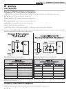
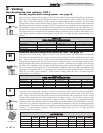
TABLE - 2I
FIELD PROVIDED TERMINATIONS
MODEL VENT SIZES MODEL VENT SIZES
PB/FN0502-F9 7" PB/FN1501-B9 12"
PB/FN0752-F9 9" PB/FN1701-B9 14"
PB/FN1002-F9 10" PB/FN2001-B9 14"
PB/FN1302-F9 12"
-- --
G
CAT I
TABLE - 2J
FIELD PROVIDED TERMINATIONS
MODEL AIR SIZES
VENT SIZES MODEL AIR SIZES VENT SIZES
PB/FN0502-F9 5" 7" PB/FN1501-B9 6" 12"
PB/FN0752-F9 5" 9" PB/FN1701-B9 7" 14"
PB/FN1002-F9 6" 10" PB/FN2001-B9 8" 14"
PB/FN1302-F9 6" 12"
-- -- --
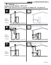
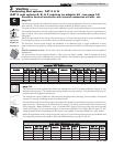
DirectAire vertical venting with vertical air inlet - see page 19.
Units that may be vented with a Category I, Type “B” vent material operate with limited burner modulation.
These units can be identified by the Category I and the control number F9 or B9 as noted on the unit’s rating
plate. These are the only units that can be vented with standard double-wall vent material. See the General
Venting and the Negative Draft General Venting sections on pages 21 and 22. The flue must terminate at the
rooftop and follow the clearance requirements on pages 27 and 28. Combustion air is supplied vertically from
the rooftop. The installation of the vent must conform to the latest edition of the National Fuel Gas Code, ANSI
Z223.1, in Canada, the latest edition of CGA Standard B149 Installation Code for Gas Burning Appliances and
Equipment. The negative draft in a conventional vent installation must be within the range of 0.02 to 0.08
inches w.c. to ensure proper operation. Make all draft readings while the unit is in stable operation
(approximately 2 to 5 minutes).
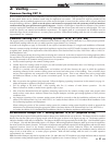
TABLE - 2K
AIR INLET CAP
MODEL
AIR
SIZES
VENT
SIZES
KIT
NUMBER
MODEL
AIR
SIZES
VENT
SIZES
KIT
NUMBER
PB/FN0502-F9 5" 7" SAK3003 PB/FN1501-B9 6" 12" SAK3004
PB/FN0752-F9 5" 9" SAK3003 PB/FN1701-B9 7" 14" SAK3005
PB/FN1002-F9 6" 10" SAK3004 PB/FN2001-B9 8" 14" SAK3006
PB/FN1302-F9 6" 12" SAK3004
--
--
-- --
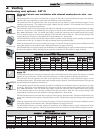
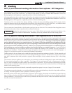
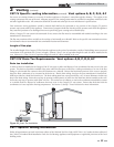
DirectAire vertical with sidewall air inlet - see page 19.
Units that may be vented with a Category I, Type “B” vent material operate with limited burner modulation.
These units can be identified by the Category I and the control number F9 or B9 as noted on the unit’s rating
plate. These are the only units that can be vented with standard double-wall vent material. See the General
Venting and the Negative Draft General Venting sections on pages 21 and 22. The flue must terminate at the
rooftop and follow the clearance requirements on pages 27 and 28. Combustion air is supplied horizontally
from the outside. The installation of the vent must conform to the latest edition of the National Fuel Gas Code,
ANSI Z223.1, in Canada, the latest edition of CGA Standard B149 Installation Code for Gas Burning Appliances
and Equipment. The negative draft in a conventional vent installation must be within the range of 0.02 to 0.08
inches w.c. to ensure proper operation. Make all draft readings while the unit is in stable operation
(approximately 2 to 5 minutes).
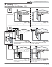
H
CAT I
I
CAT I
Air Inlet Cap


