


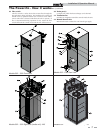
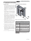

The Power-fin - How it works...
1. Heat exchanger
The heat exchanger allows system water to flow through specially
designed tubes for maximum heat transfer. The glass lined
headers and copper finned tubing are encased in a jacket that
contains the combustion process.
2. Heat exchanger access cover
The heat exchanger access cover is a stainless steel door which
allows access for service, maintenance, and removal of the heat
exchanger from inside the combustion chamber.
3. Blower
The blower pulls in air and gas through the venturi (see
item 5) and injects the fuel/air mixture into the burner, where
they burn inside the combustion chamber.
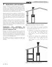
4. Gas valve
The gas valve allows the proper amount of gas to pass into the
burner for combustion. The gas valve on the Power-fin works
under a negative pressure so gas should only be pulled through
the valve when the blower is in operation.
5. Venturi
The venturi attaches to the inlet (or suction) side of the blower
and generates the negative pressure needed by the gas valve.
6. Flue sensor (not shown)
The flue sensor is mounted in the exhaust collar of the unit and
monitors the flue gas temperature. If the temperature in the
stack exceeds the maximum temperature the unit will shut
down to prevent a hazardous condition. In Category I models
the flue sensor helps to control the amount of modulation to
prevent condensation in the stack.
7. Outlet temperature sensor
This sensor monitors the outlet water temperature. If selected
as the controlling sensor, the appliance will maintain set point
by adjusting the firing rate of the unit according to this sensor.
8. Inlet temperature sensor
This sensor monitors inlet water temperature. If selected as the
controlling sensor, the appliance will maintain set point by
adjusting the firing rate of the unit according to this sensor.
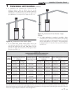
9. Temperature and pressure gauge
The temperature and pressure gauge monitors the outlet
temperature of the appliance as well as the system water
pressure.
10. Electronic display
The electronic display consists of 7 buttons and a dual line
32-character liquid crystal display used to monitor the
operation of the heater as well as enter and view the
programming of the main control board.
11. Burner (not shown)
The burner is made of a woven fabric over steel screen
construction. The burner uses pre-mixed air and gas and provides
a wide range of firing rates.
12. Water outlet (system supply)
The water outlet is a 2 1/2" pipe connection that supplies water
to the system with connections for a flow switch (see #28), a
relief valve (see #25), and a temperature and pressure gauge
(boilers only) (see #9).
13. Water inlet (system return)
The water inlet is a 2 1/2" pipe connection that receives water
from the system and delivers it to the heat exchanger.
14. Gas connection pipe
The gas pipe connection on this appliance is 1", 1 1/4", or
1 1/2" NPT. To deliver the correct amount of gas volume to the
appliance it may be necessary to have a larger gas line reduced to
1 1/4" at the appliance. Please reference the National Fuel Gas
Code charts for more details.
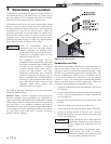
15. SMART SYSTEM Control Module
The SMART System Control Module is the main control for the
appliance. This module contains the programming that
operates the blower, gas valve, and pumps in addition to other
programmable features.
16. Air intake
The air intake pipe allows fresh air to flow directly to the
appliance. The air inlet is part of the filter box assembly where air
filtration is accomplished with a standard filter.
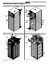
17. Line voltage terminal strip
The line voltage terminal strip provides a location to connect
all of the line voltage (120 VAC) contact points to the unit.
18. Low voltage connection board
The low voltage connection board provides a location to tie in
all of the low voltage contacts to the appliance. This is where most
of the external safety devices are connected to the unit such as
the louver proving switch.
19. Condensate trap
The condensate trap is designed to prevent flue gases from
escaping the appliance through the combustion chamber drain.
20. Access cover - front
The front access cover provides access to the gas train as well as
the blower and other key components for service and
maintenance.
21. Hot surface igniter (HSI)
The hot surface igniter is a device that is used to ignite the
air/gas mixture as well as monitor the performance of the flame
during operation. This device acts as a flame sense electrode.
22. Flame inspection window (sight glass) (not shown on
Models 502 - 1302)
The flame inspection window is a quartz glass window that
allows a visual inspection of the burner and flame during
operation.
23. Gas shut off valve (downstream test cock)
The downstream test cock is provided in the gas train to ensure
complete shut off of the gas to the burner in case of
maintenance, inspection, or testing of the valve.
24. High limit sensor
Device that monitors the outlet water temperature to ensure
safe operation. If the temperature exceeds its setting (field
adjustable), it will break the control circuit, shutting the
appliance down.
25. Relief valve
The relief valve is a safety device that ensures the maximum
pressure of the appliance is not exceeded. Boilers operate on
pressure only and are shipped from the factory at a rating of
50 PSI. Water heaters operate on temperature and pressure and
are shipped standard as 150 PSI and 210°F (98.9°C).
26. Power switch
The power switch is used to engage and disengage power to the
appliance on the 120 VAC circuit.
27. Air pressure switch - low
The air pressure switch is a safety device which ensures proper
blower operation. The air pressure switch is wired in series with
the low voltage control circuit in such a way that if the fan does not
engage or shuts down prematurely the device will break the
control circuit and the unit will shut down.
28. Air pressure switch - high
This pressure switch is only monitored during startup and serves
to ensure the blower is providing higher air flows required for
purging.
6
Installation & Operation Manual