76
10 Maintenance
Check flue gas passageways
Any sign of soot around the inner jacket, outer jacket, flue pipe
connections, burner or in the areas between the fins on the
copper heat exchanger indicates a need for cleaning. The
following cleaning procedure must only be performed by a
qualified serviceman or installer. Proper service is required to
maintain safe operation. Properly installed and adjusted units
seldom need flue cleaning.
All gaskets/sealants on disassembled
components or jacket panels must be
replaced with new gaskets/sealants on
reassembly. Gasket and sealant kits are
available from your distributor.
NOTICE
ƽ CAUTION
When a Category IV vent system is
disconnected for any reason, the flue must be
reassembled and resealed according to the
vent manufacturer’s instructions.
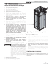
Access to the burner will require the following steps:
1. Turn off main electrical power to the appliance.
2. Turn off main manual gas shutoff to the appliance.
3. Remove the front outer control panel covers. Slide out the
inner control panel to increase service clearances and
carefully remove the multi-pin wiring connectors on the
back of the control panel. Remove the screws along the
front and rear edge of the top outer jacket panel to remove
top. Remove the control panel to allow access to
the components in the top of the appliance.
4. Remove the sensing tubes from the low air pressure switch
to the combustion air blower.
5. Disconnect the wiring connections on the top of the
combustion air blower.
6. Remove the six (6) hex head bolts attaching the gas/air
venturi to the inlet of the combustion air blower.
7. Remove the four (4) nuts holding the combustion air
blower to the top of the burner and remove the combustion
air blower assembly.
8. Use care when removing the combustion air blower
assembly to prevent damage to the venturi and burner
gaskets.
9. Disconnect the power wires to the hot surface igniter.
10. Remove the hot surface igniter. The hot surface igniter is
fragile. Use care to prevent impact damage to the silicone
carbide igniter surface when removing the igniter.
11. Remove the eight (8) nuts holding the burner to the
heat exchanger.
12. The burner can now be lifted vertically out of the heat
exchanger chamber.
13. Use care when removing the burner to prevent damage
to the woven burner port surface or gaskets on removal.
14. Remove any visible dust or dirt blockage from the
surface of the burner with a vacuum. Compressed air
may also be blown across the burner surface to clean
the “pores” of the woven burner port material.
15. Reassemble in reverse order.
Inspect and clean burner
The burner should be removed for inspection and cleaned on an
annual basis. An appliance installed in a dust or dirt
contaminated environment may require cleaning of the burner
on a 3 to 6 month schedule or more often, based on severity of
the contamination. The fan assisted combustion process may
force airborne dust and dirt contaminants, contained in the
combustion air, into the burner. With sustained operation,
non-combustible contaminants may reduce burner port area,
reduce burner input or cause non-warrantable damage to the
burner.
Use extreme care when operating an appliance for temporary
heat during new construction. Airborne contaminants such as
dust, dirt, concrete dust or drywall dust can be drawn into the
burner with the combustion air and block the burner port area.
An external combustion air filter is provided with the appliance.
This filter helps ensure clean air is used for the combustion
process. Check this filter every month and replace when it
becomes dirty. The burner of an appliance used for temporary
heat without a combustion air filter installed will probably
require a thorough cleaning before the unit is placed into
normal service.
Installation & Operation Manual


