


69
Installation & Operation Manual
Pump operation
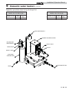
1. The water heater must have a properly sized circulating
pump. This pump is sized to circulate water between
the heater and the storage tank only.
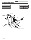
2. The pump is sized to the heater input and water
chemistry specifications noted in the Water Chemistry
section on page 64.
3. The diameter and length of the piping installed between
the storage tank(s) and water heater must be properly
sized based on the capacity of the circulating pump.
4. The pump must run continuously when the water
heater is energized. This is the standard operating
system for a water heater.
An intermittent pump control function with an all bronze pump
is installed as standard equipment on all water heater systems.
The pump will operate only while there is a “Call for Heat” and
for a timed period after the water temperature set point is
satisfied to remove any residual heat from the combustion
chamber.
5. Lubricate pump to manufacturer’s recommendations.
Pump damage due to inadequate lubrication is
non-warrantable.
The tank sensor must be installed in the tapping provided in the
lower 25% of the storage tank to achieve proper operation. As
shipped from the factory, the tank sensor is in the literature
package shipped with the unit. Placing the sensor in the tapping
provided on the storage tank will improve temperature response
and prevent short cycles of operation.
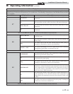
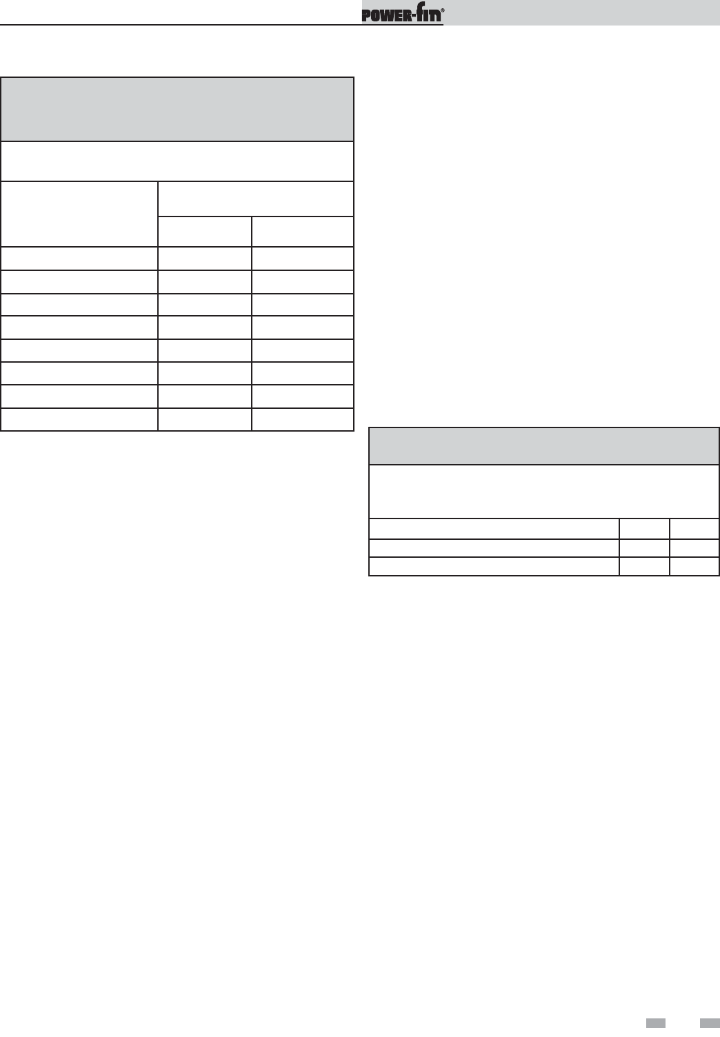
TABLE 9D
MINIMUM PUMP PERFORMANCE
Based on heating potable water with a hardness of 5 to 25
grains per gallon and total dissolved solids not exceeding
350 ppm. See Water Chemistry section on page 64.
Model GPM Ft. Hd.
502 - 752 - 1002 - 1302 75 15
1501 - 1701 - 2001 90 15
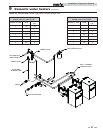
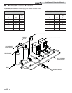
When installing multiple water heaters and/or multiple storage
tanks, the diameter of the inter-connecting pipe and all fittings
must be increased. An increase in pipe diameter will decrease
head loss in the system piping and ensure proper flow. Proper
pipe size between the heater and storage tank MUST be
maintained to ensure that the standard pump supplied on the
water heater will maintain desired flow.
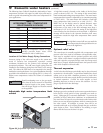
Heat exchanger
This is a highly sophisticated heat exchanger designed to carry
water in such a way that it generates a scouring action which
keeps all interior surfaces free from build-up of impurities. The
straight-line, four pass design of the copper finned tubes send
water into the headers at a properly rated velocity. The
configuration of the headers, in turn, creates a high degree of
turbulence which is sufficient to keep all contaminants in
suspension. This “scouring action” provides greater cost savings
for owners. Tubes are always able to transfer heat at peak
efficiency. Every surface within this water containing section is
of a non-ferrous material, providing clear, clean, rust-free hot
water. Straight copper tubes-finned on the outside for
maximum heat transfer and glass lined, cast iron, one piece,
cored headers make up an entirely rust-proof unit. On all
models, header inspection plugs in the heat exchanger can be
removed for field inspection and cleaning of copper tubes. The
heat exchanger may be removed from the unit.
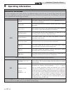
TABLE 9C
COMMON WATER MANIFOLD SIZE FOR
MULTIPLE WATER HEATER INSTALLATIONS
Pipe sizing chart provides minimum pipe size for common
manifold piping to ensure adequate flow.
Number of Water Heaters
Common Manifold Size (Min.)
Models
502 - 1302 1501 - 2001
1 2 1/2" 2 1/2"
2 3 1/2" 4"
3 4" 5"
4 5" 6"
5 6" 6"
6 6" 6"
7
6" 8"
8
8" 8"
The standard circulating pump on this water heater is sized
based on installation of a single storage tank and heater in close
proximity. If the number of fittings and straight pipe exceeds
the specified maximum equivalent number of straight feet for a
specified diameter of pipe, non-warrantable operational
problems may be experienced.
500,000 - 1,300,000 Btu/hr Models
1/2 HP, 120 VAC, 9.8 Amps
1,500,000 - 2,000,000 Btu/hr Models
3/4 HP, 120 VAC, 8.8 Amp
The standard pump selection is based on the following pipe and
fittings from the water heater to the storage tank:
6 - 90° elbows 2 - ball valves
2 - unions 1 - cold water tee
Not more than 45 feet of straight pipe.
For every elbow and tee in excess of those shown above,
DEDUCT 6.5 FEET from the maximum allowable straight pipe
in the heater to tank circulating loop.
9 Domestic water heaters (continued)