


ii
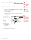
Minimum Required Connections ............................................................................................ 2-20
Section 2.4: Connecting SPI Communications .........................................................................2-21
Connecting the SPI Interface .................................................................................................. 2-21
SPI Signal Overview ................................................................................................................ 2-21
SPI Pins and Connections .......................................................................................................2-22
Logic Level Shifting and Conditioning Circuit ........................................................................ 2-23
SPI Master with Multiple MDrivePlus Microstepping ............................................................. 2-24
Section 2.5: Using the IMS SPI Motor Interface ....................................................................... 2-25
Installation .............................................................................................................................. 2-25
Configuration Parameters and Ranges .....................................................................................2-25
Color Coded Parameter Values ................................................................................................2-25
IMS SPI Motor Interface Menu Options................................................................................. 2-26
Screen 1: The Motion Settings Configuration Screen .............................................................. 2-27
MSEL (Microstep Resolution Selection) ............................................................................. 2-28
HCDT (Hold Current Delay Time) ................................................................................... 2-29
MRC (Motor Run Current) ...............................................................................................2-29
MHC (Motor Hold Current) ............................................................................................. 2-29
DIR (Motor Direction) ......................................................................................................2-29
User ID ..............................................................................................................................2-29
IMS SPI Motor Interface Button Functions ....................................................................... 2-29
Screen 2: I/O Settings Configuration Screen ...........................................................................2-30
Input Clock Type ............................................................................................................... 2-30
Input Clock Filter ............................................................................................................... 2-30
Enable Active High/Low .................................................................................................... 2-30
Warning Temperature .........................................................................................................2-30
IMS Part Number/Serial Number Screen ................................................................................2-31
Fault Indication ....................................................................................................................... 2-31
Upgrading the Firmware in the MDrivePlus Microstepping .................................................... 2-32
The IMS SPI Upgrader Screen ........................................................................................... 2-32
Upgrade Instructions ..........................................................................................................2-32
Initialization Screen ................................................................................................................. 2-33
Port Menu ..........................................................................................................................2-33
Section 2.6: Using User-Defined SPI ........................................................................................2-35
SPI Timing Notes .................................................................................................................... 2-35
Check Sum Calculation for SPI ...............................................................................................2-35
SPI Commands and Parameters...............................................................................................2-36
SPI Communications Sequence .......................................................................................... 2-37
Appendices
Appendix A: MDrive34Plus Microstepping Motor Performance .................................................A-3
Speed-Torque Curves ................................................................................................................A-3
Motor Specifications .................................................................................................................A-4
Appendix B: Planetary Gearboxes ..............................................................................................A-5
Section Overview ......................................................................................................................A-5
Product Overview .....................................................................................................................A-5
Selecting a Planetary Gearbox....................................................................................................A-5
System Inertia ...........................................................................................................................A-9
Planetary Gearbox for MDrive34Plus ......................................................................................A-13
PM81 Gearbox Ratios and Part Numbers ...........................................................................A-13
Appendix C: Connectivity .........................................................................................................A-15
MD-CC30x-001: USB to SPI Converter and Parameter Setup Cable .....................................A-15
Installation Procedure for the MD-CC30x-000 .......................................................................A-19
Installing the Cable/VCP Drivers .......................................................................................A-19
Determining the Virtual COM Port (VCP) ........................................................................A-21
Prototype Development Cable PD12-1434-FL3 .....................................................................A-22
PD10-3400-FL3 - Internal Differential Encoder ................................................................A-23
Prototype Development Cable PD02-3400-FL3 — Main Power.............................................A-24
Appendix D: Interfacing an Encoder .......................................................................................A-25
Factory Mounted Internal Encoder .........................................................................................A-25
General Specifications .............................................................................................................A-25