


2-13
Part 2: Interfacing and Configuring
S E C T I O N 2 . 3
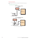
Isolated Input Interface and Connection
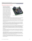
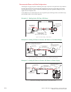
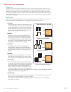
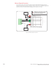
Optically Isolated Logic Inputs
The MDrivePlus
Microstepping has
three optically iso-
lated inputs which
are located at the
flying leads or on
connector P1. These
inputs are iso-
lated to minimize or
eliminate electrical
noise coupled onto
the drive control
signals. Each input
is internally pulled-
up to the level of
the optocoupler
supply and may be
connected to sinking
or +5 to +24 VDC
sourcing outputs on
a controller or PLC.
These inputs are:
1] Step Clock (SCLK)/Quadrature (CH A)/Clock UP
2] Direction (DIR)/Quadrature (CH B)/ Clock DOWN
3] Enable (EN)
Of these inputs only step clock and direction are required to operate the MDrivePlus Microstepping.
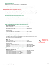
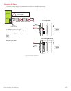
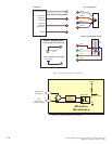
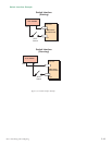
Isolated Logic Input Pins and Connections
The following diagram illustrates the pins and connections for the MDrive 17 and 23 Plus Microstepping
family of products. Careful attention should be paid to verify the connections on the model MDrivePlus
Microstepping you are using.
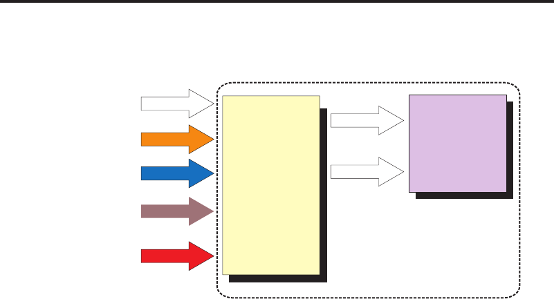
Opto Ref.
Step Clock
Direction
Enable
Power
Microstep
Driver
Enhanced
Torque
Stepping
Motor
MDrivePlus Intergrated
Motor and Microstep Driver
ØA
ØB
Figure 2.3.1: MDrivePlus Microstepping Block Diagram