


2-14
MDrive 34Plus
Microstepping Hardware - Revision R071108
Relevant to Firmware Version 3.0.02
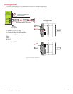
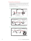
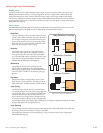
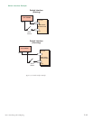
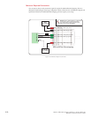
Figure 2.3.2: Isolated Input Pins and Connections
12-Pin Locking Wire Crimp
12” Flying LeadsController
P1
White
Orange
Blue
Brown
A
Pin 3
Pin 5
Pin 4
Pin 6
A
A
B
B
C
C
D
D
D
Step Clock
Channel A
Clock Up
Direction
Channel B
Clock Down
Enable
Opto Reference
B
C
A
Inputs Configured as Sinking
+5 to +24VDC
A
Inputs Configured as Sourcing
Controller I/O
Ground
See Input Configuration
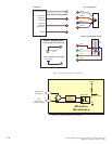
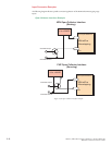
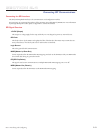
Input Configuration
Constant
Current
Source
Optocoupler
+5 VDC
To Drive Logic
Optocoupler
Reference
Input
(Step Clock,
Direction, Enable)
MDrivePlus
Microstepping
Figure 2.3.3: Optocoupler Input Circuit Diagram