


2-21
Part 2: Interfacing and Configuring
S E C T I O N 2 . 4
Connecting SPI Communications
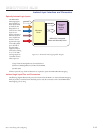
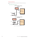
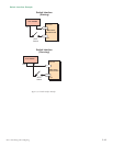
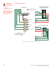
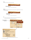
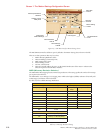
Connecting the SPI Interface
The SPI (Serial Peripheral Interface) is the communications and configuration interface.
For prototyping we recommend the purchase of the parameter setup cable MD-CC300-000. For more information
on prototype development cables, please see Appendix: C: Cables and Cordsets
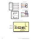
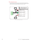
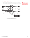
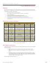
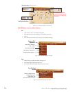
SPI Signal Overview
+5 VDC (Output)
This output is a voltage supply for the setup cable only. It is not designed to power any external devices.
SPI Clock
The Clock is driven by the Master and regulates the flow of the data bits. The Master may transmit data at a
variety of baud rates. The Clock cycles once for each bit that is transferred.
Logic Ground
This is the ground for all Communications.
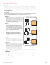
MISO (Master In/Slave Out)
Carries output data from the MDrivePlus Microstepping units back to the SPI Master. Only one MDrivePlus
can transmit data during any particular transfer.
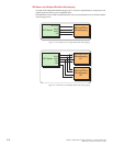
CS (SPI Chip Select)
This signal is used to turn communications to multiple MDrivePlus Microstepping units on or off.
MOSI (Master Out/Slave In)
Carries output data from the SPI Master to the MDrivePlus Microstepping.