


25 300381000
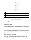
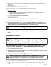
6. Reassemble check valves as shown in Figure 9. ALWAYS INSTALL NEW BALL SEAT (QUAD RING) P/N
312418000.
NOTE: Make sure when assembling check valves together, check valve female end with white tapered
gasket inside, is on inlet side of liquid double check valve assembly.
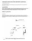
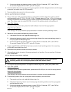
7. Assemble check valves together as shown in Figure 8 . DO NOT OVERTIGHTEN.
8. Make sure white tapered gasket is in place inside female end of liquid double check valve, then install
double check valve on elbow in water pump outlet port.
9. Connect carbonator tank water inlet line to liquid double check valve outlet.
10. Remove liquid single check valve from carbonated water tank carbonated water outlet line.
11. Disassemble check valve as shown in Figure 9.
12. Wipe each part with clean lint-free cloth. Inspect each part, especially the ball, for burrs, nicks, corrosion,
deterioration, and other damage. Discard ball seat and any damaged or suspicious parts and replace with
new parts during reassemble.
13. Reassemble liquid check valve as shown in Figure 9. ALWAYS INSTALL NEW BALL SEAT (QUAD RING)
P/N 312418-000.
14. Install check valve in carbonated water tank carbonated water outlet line.
15. Repeat procedures in Servicing Carbonator Water Pump Water Strainer Screen and this paragraph for
servicing water strainer screen and liquid check valves on other carbonator.
16. Turn carbonator CO
2
regulator adjusting screw to the right (clockwise) until its gage indicates pressure
setting observed in step 3 of Servicing Carbonator Water Pump Water Strainer Screen.
17. Open shutoff valve in plain water inlet supply line.
18. Restore electrical power to Cooling Unit at disconnect switch.
19. Dispense carbonated water at dispensing station and allow carbonators to cycle on and off. Check for
water leaks and repair if evident.
20. Disconnect electrical power from Cooling Unit at disconnect switch.
21. Install Cooling Unit left-side panel and top cover. Place unit back in operating position if moved out for
panel removal.
22. Restore electrical power to Cooling Unit at disconnect switch.
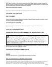
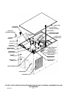
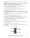
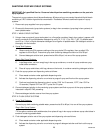
TANK BRACKET
LEVEL CONTROL
SWITCH(2)
SWITCH ADJUSTMENT
BRACKET
SWITCH ACTUATOR(2)
FIGURE 7. CARBONATOR LIQUID LEVEL CONTROL SWITCHES