


11 300381000
3. Lower Cooling Unit into operating position to complete seal from unit base to floor. Apply additional sealant
around bottom of base. Seal must have a minimum radius of 1/2-inch to prevent cracks and crevices and
to ensure a complete seal.
4. Route Cooling Unit water tank overflow hose to permanent floor drain.
5. Seal area around overflow hose where they exit from unit using permagum sealant or equivalent.
PREPARING COOLING UNIT FOR OPERATION
1. Make sure plug in end of Cooling Unit water tank drain hose is secure.
2. Open shutoff valve in plain water inlet supply line. Due to slow water fill rate of water level float control,
water tank may be hand filled until water runs out of water tank overflow hose. CLEAN
LOW-MINERAL-CONTENT WATER MUST BE USED WHERE A LOCAL WATER PROBLEM EXIST.
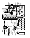
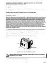
3. Adjust primary CO
2
regulator (see Figure 2) on CO
2
cylinder to a minimum nominal setting of 120-psi or
24-psi higher than highest setting required by the secondary CO
2
regulators. Loosen CO
2
regulator
adjusting screw locknut. Turn adjusting screw to the right (clockwise) until regulator gage registers nominal
120-psi, then tighten adjusting screw locknut.
4. Adjust carbonators secondary CO
2
regulator (see Figure 2) to a nominal 90-psi. Loosen CO
2
regulator
adjusting screw locknut. Turn adjusting screw to the right (clockwise) until regulator gage registers nominal
90-psi, then tighten adjusting screw lock nut. CO
2
PRESSURE TO CARBONATORS MUST NOT EXCEED
120-PSIG.
CAUTION: Before starting refrigeration system, Hydro Boostâ coil must be completely
flooded with carbonated water to prevent coil freeze-up. Proceed as follows to fill
carbonated water system.
5. Make sure both carbonated water shutoff valves inside Cooling Unit (see Figure 2) are in ‘‘OPEN’’ (handles
in line with tubing) positions.
6. Make sure Hydro Boostâ bypass valve inside Cooling Unit (see Figure 2) is in ‘‘CLOSED’’ (handle not in
line with tubing) position.
7. Make sure Cooling Unit REFRIGERATION POWER, CARBONATOR MOTORS, and CIRCULATING
MOTOR Power switches are in ‘‘OFF’’ (down) positions.
8. Connect electrical power to Cooling Unit at disconnect switch.
9. Place CARBONATOR MOTORS power switch in ‘‘ON’’ (up) position to start carbonators.
10. Dispense from dispensing station until carbonated water appears at valve indicating Hydro Boostâ and
carbonated water system have been completely filled with carbonated water.
OPERATION
WARNING: Disconnect electrical power to Cooling Unit and Remote Condenser Coil and
Fan Assembly (if applicable) to prevent personal injury before attempting any Cooling Unit
or Remote Condenser Coil and Fan Assembly internal maintenance. Only qualified
personnel should service internal components or electrical wiring.