


300381000 12
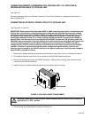
STARTING COOLING UNIT REFRIGERATION SYSTEM
NOTE: As ice bank forms in water tank, water expansion will take place and excess water will escape
through water tank overflow hose to permanent floor drain.
Cooling Unit Connected To Remote Condenser Coil and Fan Assembly. (P/N 309602000).
Place Cooling Unit REFRIGERATION POWER switch in ‘‘ON’’ (up) position. Refrigeration compressor,
compressor cooling fan, agitator motor, and Remote Condenser Coil and Fan Assembly will start. Cooling Unit
will begin forming an ice bank and refrigerated Hydro Boostâ coil will also be chilling water. When full ice bank
has been formed, Remote Condenser oil and Fan Assembly, Cooling Unit compressor, and compressor cooling
fan will stop but agitator motor will continue to operate circulating ice water bath in water tank.
Standard Cooling Unit Utilizing Condenser Coil and Fan Assembly.
Place Cooling Unit REFRIGERATION POWER switch in ‘‘ON’’ (up) position. Refrigeration compressor,
condenser fan motor, and agitator motor will start and begin forming an ice bank. When full ice bank has been
formed, compressor and condenser fan motor will stop but, agitator motor will continue to operate circulating ice
water bath in water tank.
STARTING CARBONATED WATER CIRCULATING PUMP
1. Place CIRCULATING MOTOR power switch in ‘‘ON’’ (up) position. Circulating pump will start and begin
circulating carbonated water in system.
2. Dispense carbonated water from dispensing valve to make sure all air has been purged from system.
3. If Cooling Unit plain water outlet line is connected to dispensing system, open plain water shutoff valve
inside unit. Dispense from valve until all air is purged from plain water system.
ACTIVATING SYRUP SYSTEMS
1. Adjust soft drink tanks secondary CO
2
regulators (see Figure 2) as follows:
Sugar Syrup Soft Drink Tanks CO
2
Regulator.
Adjust sugar syrup soft drink tanks secondary CO
2
regulator at 40-psig for syrup lines up to 10-feet in
length plus one pound for each additional length of 10-feet, plus one pound for each 2-feet of vertical lift.
For example: if syrup line total length is 30-feet and total vertical lift is 6-feet, then 40-psig + 2-psig
(1-pound for every 10-feet of length over 10-feet which is 20-feet) + 3-psig (1-pound for every 2-feet of
vertical lift which is 6-feet); total equals 40 + 2 + 3 = 45-psig CO
2
regulator setting.
Low-Calorie (diet) Syrup Soft Drink Tank CO
2
Regulator.
Adjust low-calorie (diet) soft drink tank secondary CO
2
regulator for low-calorie drink at 10-psig for syrup
lines up to 30-feet in length. Syrup lines longer than 30-feet in length may require a slightly higher CO
2
regulator setting to 12-psig maximum. Excessive CO
2
pressure may cause low-calorie syrup carbonation
resulting in foam.
IMPORTANT: Syrup systems must be sanitized as instructed before syrup is connected into syrup
systems.
2. Connect soft drink tanks into syrup systems.
3. Dispense from all dispensing stations dispensing valves until product is dispensed.