


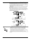

ANTENNA
MOUNT
(2 PLACES)
ANTENNA
(2)
SCREW
(2)
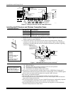
BLACK
MOUNTING
CLIP
RED
MOUNTING
CLIP
WHITE
MOUNTING
CLIP
GROUNDING
LUG
(2)
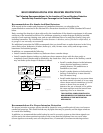
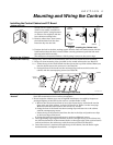
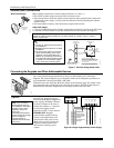
NOTE
A COMBINATION OF THESE MOUNTING CLIPS HAS BEEN
INCLUDED IN YOUR INSTALLATION KIT.
USE THE APPROPRIATE CLIPS FOR MOUNTING.
IF NO RF RECEIVER IS USED, MOUNT THE PC BOARD USING
EITHER THE WHITE OR BLACK CLIPS, WHICHEVER ARE
INCLUDED IN THE CONTROL PANEL'S HARDWARE KIT.
DETAIL A
SIDE VIEW
OF BOARD -
SUPPORTING SLOTS
CIRCUIT
BOARD
CABINET
MOUNTING
CLIP
CABINET
MOUNTING
CLIP
CONTROL
CIRCUIT
BOARD
BOARD
SUPPORTING
SLOTS
RECEIVER CIRCUIT BOARD
++
AB
pc_mount-001-V1
DETAIL B
ANTENNA AND GROUNDING
LUG INSTALLATION
INSTALLATION WITH RECEIVER CIRCUIT BOARD
Figure 3. Mounting the PC Board and RF Receiver
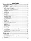
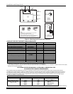
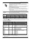
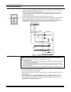
AUXILIARY DEVICE CURRENT DRAW WORKSHEET
DEVICE CURRENT No. UNITS TOTAL CURRENT
6150 Fixed-Word Keypad 40mA/70mA**
6160 Alpha Keypad 40mA/150mA**
6150V Fixed-Word Display Voice Keypad 60mA/160mA**
6160V Alpha Display Voice Keypad 60mA/190mA**
8132/8142 Series AUI (Symphony) 150mA/400mA**
6270 Touch Screen Keypad 180mA/280mA**
5881/5882 RF Receiver 60mA
5883 Transceiver 80mA
4219 Zone Expander 30mA
4204 Relay Unit
15/180mA
‡
4229 Zone Expander/Relay Unit
30/100mA
‡
4285 Phone Module 160mA
4286 Phone Module 300mA
*
(Current available from Aux. terminals = 600 mA max.)
†
TOTAL =
*If using hardwire devices such as PIRs, refer to the specifications for that particular unit's current draw.
** Values are for standby/alarm; alarm for keypads means armed with backlighting on and sounder on
†In UL installations, maximum current draw from the Auxiliary Output and the Alarm Output combined must not exceed 600 mA (500 mA max from Aux. Output).
‡Values are for relays OFF/relays ON.
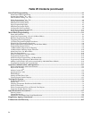
CALIFORNIA STATE FIRE MARSHALL (CSFM) AND UL RESIDENTIAL FIRE
24-HOUR BATTERY BACKUP REQUIREMENTS
The California State Fire Marshal and UL have regulations which require that all residential fire alarm control panels must be
provided with a backup battery which has sufficient capacity to operate the panel and its attached peripheral devices for 24 hours in
the intended standby condition, followed by at least 4 minutes in the intended fire alarm signaling condition. This control panel can
meet these requirements without using a supplementary power supply, provided that the panel’s auxiliary power and bell output
currents are limited as indicated below.
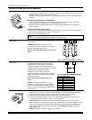
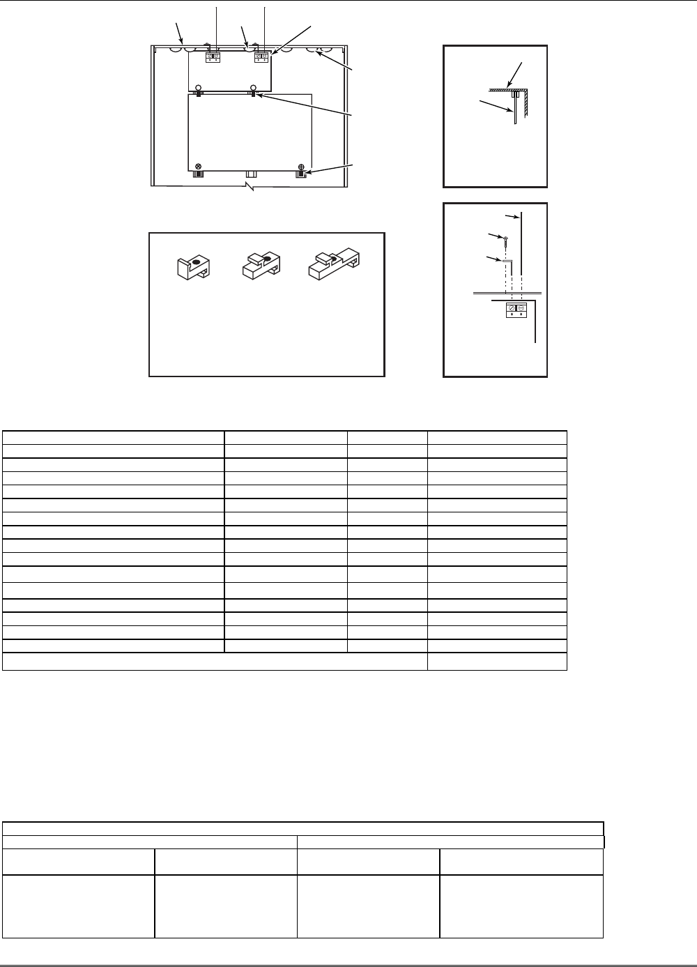
OUTPUT LIMITATIONS AND CORRESPONDING REQUIRED BATTERIES
OUTPUT CURRENT LIMITATIONS BATTERY INFORMATION
Output Current Total Maximum Auxiliary Current Battery Capacity
To Use (Amp/Hrs)
Recommended Battery
(Yuasa Model No.)
600mA maximum total of
auxiliary power plus bell
output currents
45mA
160mA
200mA
425mA
500mA
4AH
7AH
8AH
14AH
17.2AH
NP4-12 (or ADEMCO 467)
NP7-12
NP4-12 (two) ‡
NP7-12 (two) ‡
NPG18-12
‡ NOTE: Use two batteries, connected in parallel. Obtain an Ademco Battery Harness Kit SA5140-1. (Both batteries will fit inside the cabinet.)
Installation and Setup Guide
2-2