


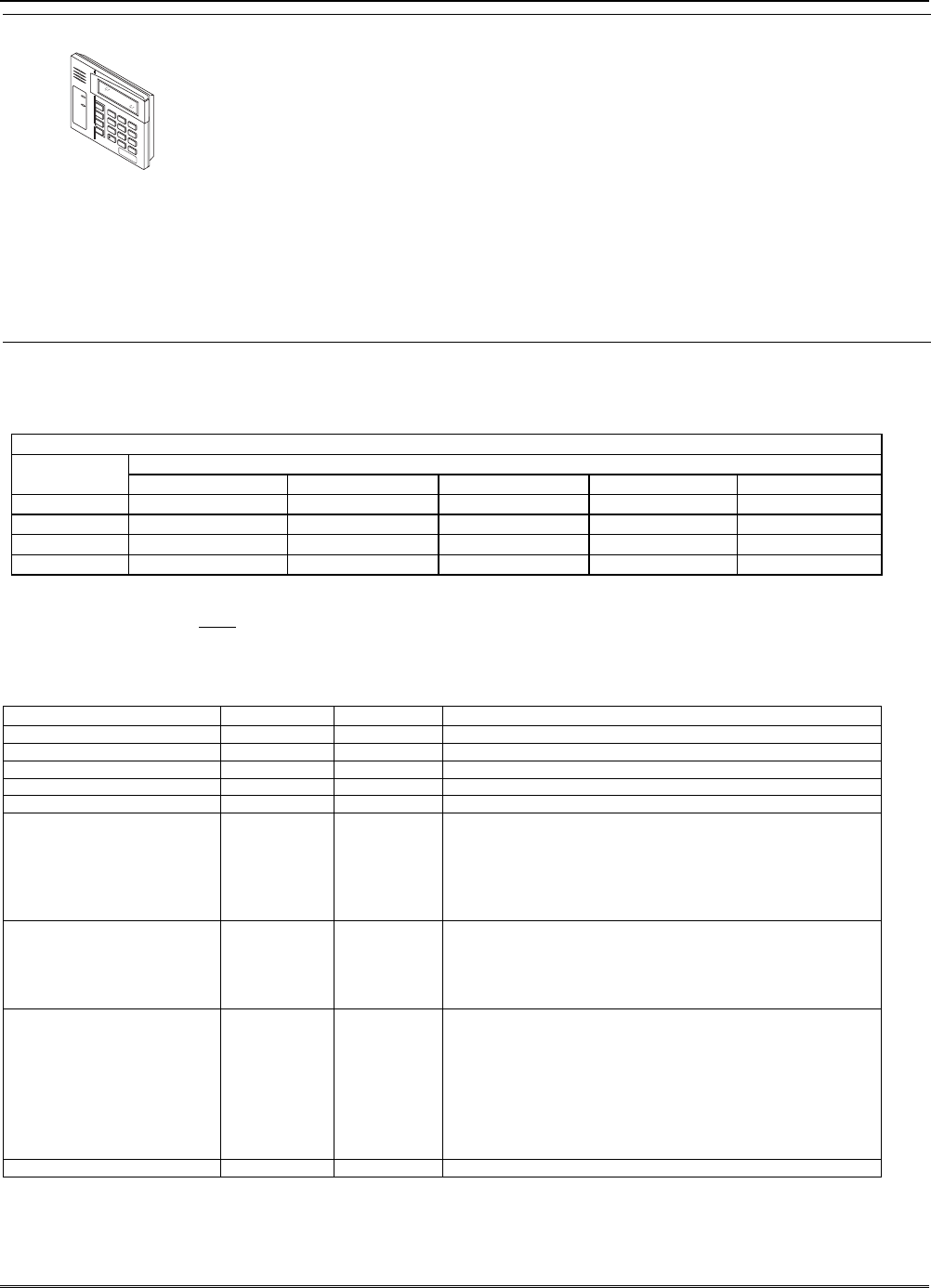
Keypad Notes
ARMED
READY
1
O
F
F
4
M
A
X
7
IN
ST
ANT
R
E
A
D
Y
2
A
W
A
Y
5
T
E
S
T
8
C
O
D
E
0
3
S
T
A
Y
6
B
Y
P
A
S
S
9
C
H
I
M
E
#
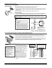
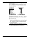
Set device addresses. Refer to the instructions included with the devices and set each
address according to the Table of Devices Addresses.
See Keypad Programming Fields (fields *190-*196) in Section 4. Data Field
Programming for details on enabling keypad addresses, assigning keypad partitions
and selecting keypad sounding options.
IMPORTANT: Each keypad must be assigned a unique, predefined address, from 16 to
23. The first keypad is address 16 (default = partition 1, all sounds enabled).
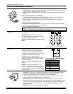
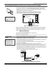
TOUCH SCREEN KEYPAD (AUI) NOTES:
•
••
• Use of up to 2 AUI devices (e.g., 6270, Symphony) is independent from standard
keypads and does not affect the number of standard keypads the system can support.
•
••
• AUI devices must be set for either address 1 or address 2, depending on which unit is
enabled in field *189.
•
••
• To ensure proper AUI device operation, connect only to controls having microprocessor
version 3.0 or higher, and use AUI devices with the following rev levels: 6270 series
use version 1.0.9 or higher; 8132/8142 (Symphony) series use version 1.1.175 or higher.
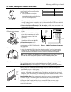
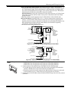
Long Range Radio
Connections
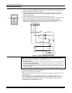
Connect the data in/data out terminals and voltage input terminals of the Long Range
Radio to the control's keypad connection points.
Set the radio’s address to “03” following the instructions provided with the radio.
• Use compatible Long Range Radios (e.g., 7720PLUS, 7820, 7835C, or 7845C).
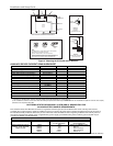
Wire Run Chart For Devices* Drawing Aux Power From The Control (12V+ & 12V–)
Wire
TOTAL CURRENT DRAWN BY ALL DEVICES CONNECTED TO A SINGLE WIRE RUN
Size 50 mA or less 100 mA 300 mA 500 mA 600 mA
#22 900 ft (274m) 450 ft (137m) 150 ft (46m) 90 ft (27m) 75 ft (23m)
#20 1400 ft (427m) 700 ft (213m) 240 ft (73m) 140 ft (43m) 120 ft (37m)
#18 1500 ft (457m) 1100 ft (335m) 350 ft (107m) 220 ft (67m) 170 ft (52m)
#16 1500 ft (457m) 1500 ft (457m) 550 ft (168m) 350 ft (107m) 270 ft (82m)
* Includes Keypads, RF Receivers, Zone Expander/Relay Units, 4285/4286 Phone Module, and Long Range Radio.
Maximum wire lengths for any device that is homerun to the control can also be determined from the Wiring Run Chart, based on the
current draw of that device alone
.
The length of all wire runs for both partitions combined must not exceed 1500 feet (457m) when unshielded quad conductor cable is used
(750 feet if shielded cable is used). This restriction is due to the capacitive effect on the data lines when quad cable is used.
Table of Device Addresses
This Device Uses Address
Reports as
††
Enabled By…
RF Receiver 00 100 *56 zone programming: input device type entry
AUI 1 01 101 automatic if AUI enable field *189 enabled for AUI 1
AUI 2 02 102 automatic if AUI enable field *189 enabled for AUI 2
Long Range Radio 03 103 automatic if output to long range radio field *29 enabled
4286 Voice Module 04 104 automatic if phone module access code field *28 enabled
Zone Expanders (4219/4229):
module 1 (for zones 09 - 16)
module 2 (for zones 17 - 24)
module 3 (for zones 25 - 32)
module 4 zones 33 - 40
module 5 zones 41 - 48
07**
08
09
†
10
†
11
†
107
108
109
110
111
*56 zone programming: input device type, entry 2, then:
automatic if zone no. 9-16 set as AW type or relay assigned
automatic if zone no. 17-24 set as AW type or relay assigned
automatic if zone no. 25-32 set as AW type or relay assigned
automatic if zone no. 33-40 set as AW type or relay assigned
automatic if zone no. 41-48 set as AW type or relay assigned
Relay Modules (4204):
module 1
module 2
module 3
module 4
12
13
14
†
15
†
112
113
114
115
*79 output device programming: device address prompt:
entered at device address prompt
entered at device address prompt
entered at device address prompt
entered at device address prompt
Keypads:
keypad 1
keypad 2
keypad 3
keypad 4
keypad 5
keypad 6
keypad 7
keypad 8
16
17
18
19
20
21
22
23
n/a
n/a
n/a
n/a
n/a
n/a
n/a
n/a
data field programming as listed below:
always enabled for partition 1, all sounds enabled.
data field *190
data field *191
data field *192
data field *193
data field *194
data field *195
data field *196
5800TM Module 28 n/a automatic
** address 07 not available if zone-doubling enabled
† 4219/4229 addresses 9-11 and 4204 addresses 14-15 apply to the VISTA-20P.
†† Addressable devices are identified by “1” plus the device address when reporting. Enter a report code for zone 91 to enable
addressable device reporting (default = reports enabled). See field *199 for addressable device (ECP) 3-digit/2-digit identification
keypad display options.
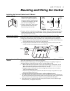
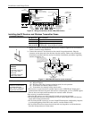
Mounting and Wiring the Control
2-5