


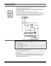

Phone Line/Phone Module, and Audio Alarm Verification (AAV) Connections
Phone Line
Connect incoming phone line and handset wiring to the main terminal block (via an
RJ31X jack) as shown in the Summary of Connections diagram at the back of this
manual.
Wire colors represent the colors of the cable to the RJ31X jack.
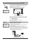
4285/4286 Phone Module
Compatibility: 4286 Phone
Modules must have
software version WA4286-
15.1 or higher (refer to the
label on the square 4286
microprocessor chip).
U
L
The 4285 and 4286
modules are UL Listed only
for use on residential fire
and UL residential burglar
alarm installations.
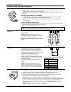
1. Make 12V (+) and (–) and data in and data out connections from the phone module to
the control, using the connector cable supplied with the phone module, then insert
the keyed connector at the other end of the connector cable into the header on the
phone module.
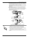
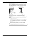
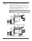
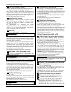
2. Connect Phone Module terminals as shown below. Use an RJ31X jack with a direct-
connect cord and make all connections exactly as shown.
3. Caller ID Units: If a Caller ID unit is being used, connect the unit directly to the
“Handset” terminals (21 & 22) on the control, as shown.
ANSWERING
MACHINE
TERMINALS
ON CONTROL
TO EARTH GROUND (COLD WATER PIPE, ETC.)
UNUSED
KEYED
HEADER
4285/4286
VIP MODULE
123456 7
YELLOW: TO DATA OUT (term. 7)
NOCONNECTION
RED: TO AUX (+) (term. 5)
BLACK: TOAUX. GROUND (–) (term.4)
GREEN: TO DATA IN (term. 6)
CONNECTOR
WITH FLYING
LEADS
TO CONTROL
PANEL
TERMINALS
USED FOR
KEYPAD
CONNECTIONS
PREMISES ANSWERING
MACHINE AND PHONES
HANDSET
INCOMING
TELCO LINE
TIP
RING
PLUG
DIRECT
CONNECT
CORD
TIP
RING
GROUND
(TIP)
(RING)
GREEN (TIP)
RED (RING)
INCOMING TELCO LINE
GREY (R)
BROWN (T)
4285/4286
TERMINAL ASSIGNMENTS
1 - TIP
2 - RING
PHONE INPUT
3 - TIP
4 - RING
PHONE OUTPUT
5 - NO CONNECTION
6 -
7 -
AUDIO OUT
4286 ONLY
}
}
}
{
{
IMPORTANT NOTE FOR
EXISTING INSTALLATIONS:
EXISTING WIRES
CONNECTED TO THE
"HANDSET" TERMINALS ON
CONTROL MUST BE MOVED
FROM THERE TO TERMINALS
3 AND 4 ON THE 4285/4286.
*
*
*
NOTE: IF THE TELEPHONE HAS BUILT-IN CALLER ID,
THE CALLER ID FUNCTION MAY NOT WORK
.
CA38A
IN
CANADA
4286_cntrl-001-V0
LOUDER
VOLUME
(4286
ONLY)
21 22 23 24 25
CALLER ID
UNIT
RJ31X
JACK
Figure 16. 4285/4286 Phone Module Wiring Connections
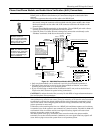
• Only one phone module can be used and it can only be connected to partition 1.
• The phone lines must be in service for the phone module to function, even when
accessing the system from an on-premises phone.
• If you are also using an Audio Alarm Verification (AAV) unit, refer to Audio Alarm
Verification (AAV) section for special wiring connections.
CAUTION: To reduce the risk of fire, use only No. 26 AWG or larger telecommunication
line cord for phone line connections.
Phone Module Problems
If no touch tones are produced following access to the security system from on-premises
(this problem may arise in rare cases), it may be necessary to reverse the wires connected
to terminals 3 and 4 on the phone module and the wires connected to terminals (21) &
(22) on the control. The wiring diagram shows the wiring connections that will provide
proper operation in most cases.
Connection to the incoming telco line via a RJ31X jack and direct-connect cord, as shown,
is essential, even if the system is not connected to a central station. The 4285 or 4286 will
not function if this is not done and an error signal (fast busy signal) will occur when
trying to access the system via the phone.
The house phone lines (gray and brown wires) must be wired to the phone module
terminals; not to the control terminals. Otherwise, an error signal (fast busy signal) will
occur when trying to access the system from an on-premises phone.
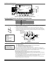
Mounting and Wiring the Control
2-13