


Connecting Relay Modules, Powerline Carrier Devices and Output Triggers
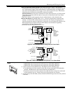
4204/4229 Relay Modules
U
L
For UL installation
requirements, refer to the
Installation Instructions for
the 4204.
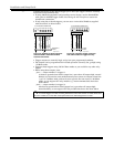
1. Mount either remotely or in the control panel.
2. Connect each module to the control’s keypad terminals and set the device addresses
as previously described in the Connecting Keypads and Other Addressable
Device section. Use the connector harness supplied with the module. Use standard
4-conductor twisted cable for long wiring runs.
VISTA-20P: Up to 16 relays (if no powerline carrier devices are used)
VISTA-15P: Up to 8 relays (if no powerline carrier devices are used)
3. Connect the desired field wiring to the unit's relay contact terminals.
TB2
121110
9
87654321
(–) GROUND
(+) 12V
YEL
BLK
GRN
RED
13 14 15 16
DIP SWITCH
FOR SETTING DEVICE ADDRESS
AND ENABLING/DISABLING TAMPER
COVER TAMPER (REED) SWITCH
TB1
4204
4-PIN TOUCHPAD PLUG
3
2
RELAY
1
4
TYPICAL
(SHOWN "OFF")
C
NC
NO
C
NC
NO
C
NC
4204_conn-1-V0
NC
NO
C
NC
NO
EITHER OR BOTH
CAN BE USED
DATA IN
FROM CONTROL
DATA OUT
TO CONTROL
RELAY
RELAY
RELAY
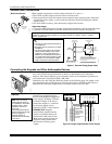
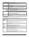
Figure 13. 4204 Connections to Control
• Supervision: 4204 and 4229 modules are supervised against removal. The module’s
device address is displayed as follows if a module is disconnected from the control’s
terminals, or if the module cover is removed and the tamper jumper is installed:
Alpha: CHECK xx Wire Expansion
FAULT xx Wire Expansion
ALARM xx Wire Expansion
Fixed-Glass: lxx (or 91 if field *199 set for 2-digit display)
where “xx is the module’s address.
• If communication/tamper failure occurs on a device with zones wired to it, all zones on
the device will be displayed in their respective partitions.
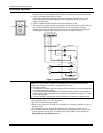
Powerline Carrier
Devices
U
L
Powerline Carrier
devices and the 1361X10
Transformer are not UL
Listed for fire or burglary
functions and are intended
for home automation.
1. Install the powerline carrier devices according to the instructions included with each.
VISTA-20P: Up to 16 devices (if no relays are used)
VISTA-15P: Up to 8 devices (if no relays are used)
2. Use Programming Mode to enter the device house ID in data field*27, and enter the
unit code using *79 Output Device menu Mode.
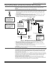
3. See connections diagram in the AC Wiring section for connecting the 1361X10
transformer to the triggers.
• You must use a 1361X10 Transformer instead of the 1321 Transformer.
• The 1361X10 Transformer provides AC power to the control panel, and also supplies
signals from the control panel through the premises AC wiring to the Powerline
Carrier devices (which are plugged into AC outlets). You can then make devices that
are plugged into Powerline Carrier devices perform various functions in response to
commands you enter at the security system keypads.
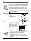
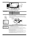
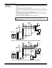
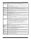
Canada: Use the PSC04 Powerline Interface as shown below.
1 2 3 4
SA4120XM-1 CABLE
X-10 PSC04
POWERLINE INTERFACE
YEL
RED
GRN
BLK
MODULAR PHONE CORD (not supplied)
1 - BLACK
2 - RED
3 - GREEN
4 - YELLOW
SYNC
DATA
COM
1345678
KEY
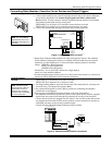
+12 AUX.
DATA
COM
SYNC
GND (-)
OUTPUT 17
(RED)
OUTPUT 18
(GREEN)
(ORANGE)
(YELLOW)
(BLUE)
(PURPLE)
(BLACK)
8-PIN TRIGGER CONNECTOR
Figure 14. PSC04 Powerline Interface Connections
Mounting and Wiring the Control
2-11