


Hardwire Zones and Zone Expansion
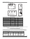
Hardwire Zones
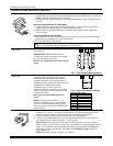
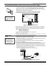
zones-001-V0
HI
LO
Normally Open Zones/ N.O. EOLR Zones
1. Connect open circuit devices in parallel across the loop; for EOLR zones, connect the
EOLR across the loop wires at the last device.
2. Enable normally open/EOLR zones using Zone Programming mode, “Hardwire Type”
prompt.
Normally Closed Zones/ N.C. EOLR Zones
1. Connect closed circuit devices in series in the high (+) side of the loop; for EOLR
zones, connect the EOLR in series following the last device.
2. Enable normally closed/EOLR zones using Zone Programming mode, “Hardwire
Type” prompt.
End of Line Resistor (EOLR) Notes
• If the EOLR is not at the end of the loop, the zone is not properly supervised and the
system may not respond to an “open” on the zone.
• Zone 1 is intended for EOLR only.
U
L
For UL commercial burglar alarm installations, use EOLR zones.
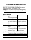
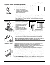
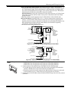
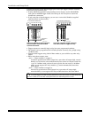
Double-Balanced Zones
(V20P only)
Connect as shown below (resistor provided
for one device).
IMPORTANT: Double-balanced zones
provide zone tamper protection, and should
be used as burglary zones only.
Do not use double-balanced zones as fire
zones.
2k
2k
2k
ZONE 3
2k
2k
2k
ZONE 4
12 13
14
zone-002-V0
TAMPER
CONTACTS
TAMPER
CONTACTS
Fig. 7. Typical Double Balanced Zones
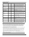
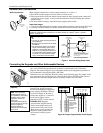
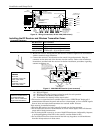
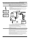
Zone Doubling
(V20P only)
This feature provides two hardwired
normally closed zones for each standard
hardwired zone connected to the control’s
terminals (but does not increase the total
number of zones supported by the control). If
enabled (Zone Programming mode,
“Hardwire Type” prompt, option “3”),
hardwire zones are automatically paired as
shown in the table. Connect as shown below
(resistors provided).
•
••
• Do not use zone doubling for fire
zones.
NOTE: A short across the EOL (i.e., at
terminal) on either zone of a zone-doubled
pair or on a double-balanced zone causes a
tamper condition (displayed as CHECK plus
zone numbers).
10 11
6.2k
ZONE 10
3k
ZONE 2
zone-004-V0
Fig. 8. Typical Zone Doubling Wiring
Zone Doubling Table
Zone Paired with zone
2 10
3 11
4 12
5 13
6 14
7 15
8 16
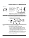
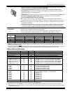
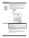
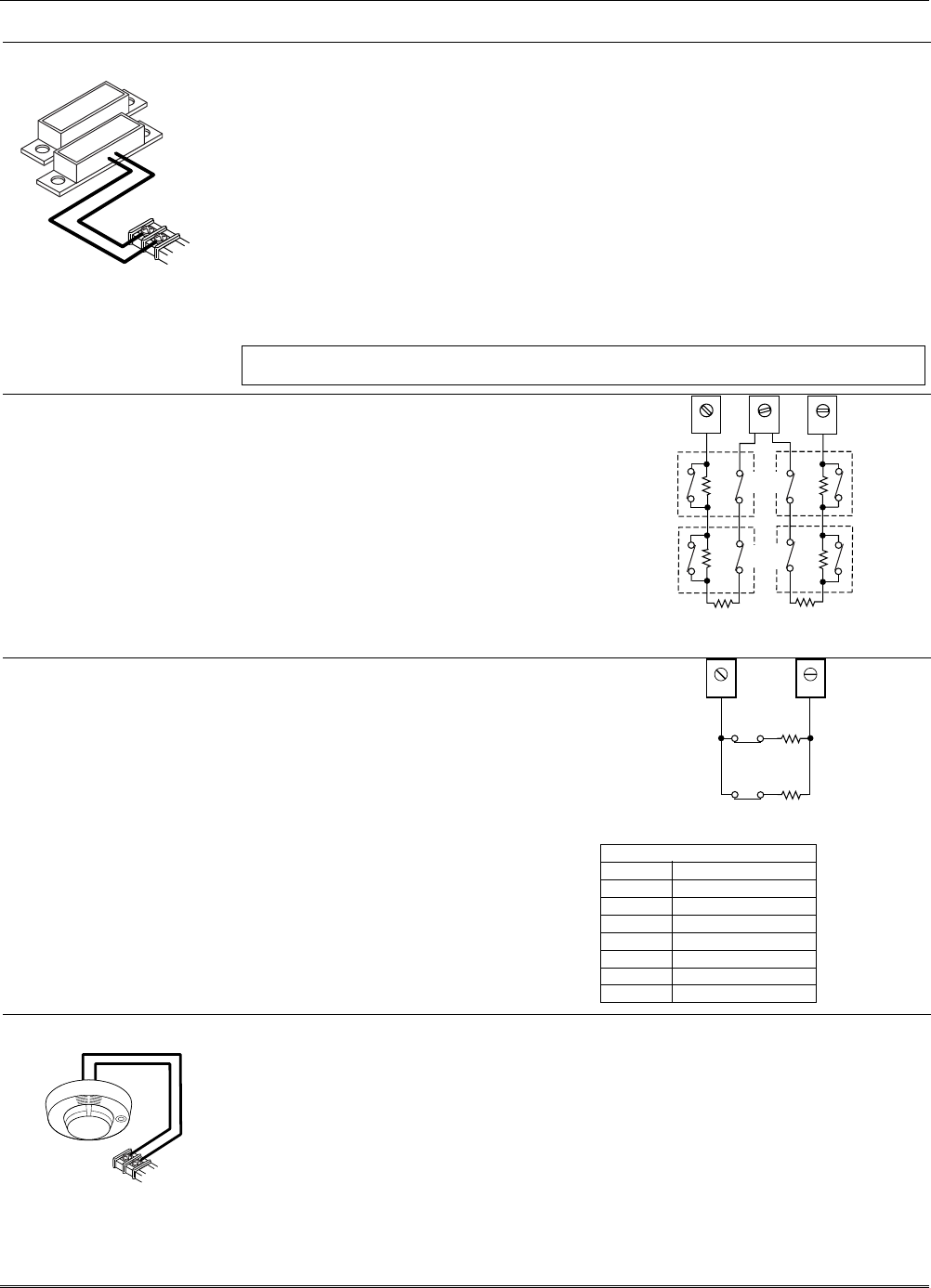
Smoke Detectors
5806-001-V0
8
9
HI
LO
TO ZONE 1
TERMINALS
2-WIRE
SMOKE
DETECTOR
ZONE 1
1. Connect up to 16 (10, if “clean me” option used) 2-wire smoke detectors across zone 1
terminals 8 (+) and 9 (-) as shown in the Summary of Connections diagram at the
back this manual. Observe proper polarity when connecting the detectors.
2. Connect an EOL resistor across the loop wires at the last detector.
3.
Connect 4-wire smoke detectors (up to 16, depending on detector current draw) to
any zone from 2-8 as shown in Figure 7 (on next page).
Power Reset: This control does not automatically reset power to 4-wire smoke
detector zones, so you must use a relay (e.g., 4204, 4229), or on-board trigger to reset
power (also required for fire verification). Do this by programming the designated
relay/trigger as zone type 54 (fire zone reset); see On-Board Trigger section for
other information.
NOTE: Maximum current on trigger 17 is 100mA.
Installation and Setup Guide
2-6