


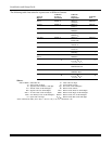


NOTES: • All BR type units must physically be activated to clear the display.
• When one button of a transmitter (RF, UR, or BR) is activated, all zones assigned to other
buttons on that transmitter are cleared from the display. This also applies to 5816 and
5817 transmitters, which have multiple loops (zones).
• Any transmitter that is not “enrolled” will not turn off its zone number.
Go/No Go Test Mode
The Go/No Go Test verifies adequate RF signal strength from the proposed transmitter location, and allow
you to reorient or relocate transmitters if necessary, before mounting the transmitters permanently. This
mode is similar to the Transmitter Test mode, except that the wireless receiver gain is reduced. This will
enable you to make sure that the RF signal from each transmitter is received with sufficient signal
amplitude when the system is in the normal operating mode.
1. Enter [Installer code] + [#] + 4 from the partition being tested. For multi-partition systems, repeat this
test for each partition.
2. After you have placed transmitters in their desired locations and the approximate length of wire to be
run to sensors is connected to the transmitter's screw terminals (if used), fault each transmitter. Do not
conduct this test with your hand wrapped around the transmitter, as this will cause inaccurate results.
a. The keypad will beep three times to indicate signal reception and display the zone number.
b. If the keypad does not beep, you should reorient or move the transmitter to another location.
Usually a few inches in either direction is all that is required.
4. If each transmitter produces the proper keypad response when it is faulted, you can then permanently
mount each of the transmitters according to the instructions provided with them.
5. Exit the Go/No Go Test mode by entering: [any user code (partition-specific)] + OFF.
Dialer Communication Test and Periodic Test Reports
1. Enter Installer Code + 5 [TEST], then press “1” at the prompt to start the Dialer Test.
1=DIAL, 0=WALK (no special display on Fixed-Word keypads)
The following will be displayed (accompanied by 2 beeps) if test is successful:
PHONE OKAY (“Cd” displayed on Fixed-Word Display Keypads)
A Contact ID report will also be sent (code 601)
If the dialer test is unsuccessful, “COMM FAILURE” (or FC) is displayed.
2. Enter Installer code + OFF to clear the display and exit.
Automatic Periodic Test Report
The system can be set to automatically send test reports (enabled in field *64; Contact ID code 602) at
specified intervals. Frequency of the reports is set in Scheduling mode (event 11) or by the following key
commands:
installer code + [#] + 0 + 0 = test report sent every 24 hours
installer code + [#] + 0 + 1 = test report sent once per week
installer code + [#] + 0 + 2 = test report sent every 28 days
Each mode sets schedule 32 (VISTA-20P) or schedule 08 (VISTA-15P) to the selected repeat option; the first
test report is sent 12 hours after command.
To ensure that test reports are sent at the times expected, set the Real-Time Clock to the proper time
before entering the test report schedule command.
Automatic Standby Battery Tests
1. An automatic test is conducted every 3 minutes to ensure that a standby battery is present and
properly connected. If a battery is not present or is not properly connected, a “LOW BATTERY”
message is displayed and, if so programmed, will be reported to the central station.
2. A battery capacity test is automatically conducted for 2 minutes every 4 hours, beginning 4 hours after
exiting the Programming mode or after powering up the system. In addition, entry into the Test mode
will also cause a battery capacity test to be initiated. If the battery cannot sustain a load, a “Low
Battery” message is displayed and, if so programmed, will be reported to the central station.
Installation and Setup Guide
7-2