


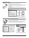
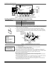

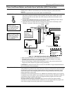
BRN
GRN
BLK
(–) GROUND
RED
(+) 12VDC
YEL
4
3
2
1
ZONES
A
B
C
D
F
GH
DIP SWITCH
FOR SETTING ADDRESS
AND ZONE "A" RESPONSE
TAMPER JUMPER POSITION
4229 IN CABINET
(NOT TAMPER)
4229 REMOTE
(TAMPER PROTECTED)
TB1
4229
TB2
WHT
GRY
VIO
BLK
YEL
ORG
NO
NC
C
GND
NO
NC
C
RLY
1
RLY
2
RELAYS OFF
RELAY
CONNECTOR
RELAY
2
RELAY
1
(TERM 6)
(TERM 4)
(TERM 5)
(TERM 7)
NO C NC
TERMINALS ON
CONTROL PANEL
1
2
3
4
DATA OUT (>)
TO CONTROL
DATA IN (<)
FROM
CONTROL
5
8
11
REED
(TAMPER)
SWITCH
2
E
1
3
4 6
7
9
10
12
TERMINATE EACH
PROGRAMMED ZONE
WITH 1000 OHM (1K)
END-OF-LINE RESISTOR
(EACH ZONE'S MAX.
LOOP RESISTANCE
300 OHMS + EOL)
4-PIN CONSOLE PLUG
EITHER OR BOTH CAN BE USED
4229-002-V0
Figure 10. Wiring Connections, 4219 & 4229 (4229 shown)
Installing the RF Receiver and Wireless Transmitter Zones
Compatible Receivers
Use any ADEMCO 5800 Series Wireless Receivers, such as:
RF Receiver No. of Zones
5881L/5882L up to 8
5881M/5882M up to 16
5881H/5882H, VISTA-20P = up to 40 plus 16 buttons
5883, 6150RF VISTA-15P = up to 26 plus 8 buttons
Receiver Connections
WIRELESS ZONE
NUMBERS
VISTA-20P:
transmitter zones 9-48
button zones 49-64
VISTA-15P:
transmitter zones 9-34
button zones 49-56
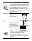
1. Set Device Address to “00” (set all switches to the right, “off” position).
2. Mount the receiver, noting that the RF receiver can detect signals from transmitters
within a nominal range of 200 feet.
3. Connect the receiver's wire harness to the control's keypad terminals. Plug the
connector at the other end of the harness into the receiver. Refer to the installation
instructions provided with the receiver for further installation procedures regarding
antenna mounting, etc.
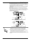
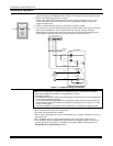
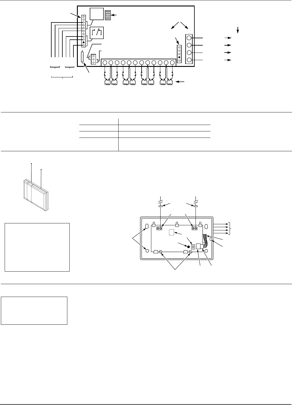
MOUNTING
HOLES
INTERFERENCE
INDICATOR
LED
CIRCUIT BOARD
DIP
SWITCH
ANTENNAS
(INSERT IN
RIGHT-HAND
TERMINALS)
YELLOW
RED
BLACK
GREEN
WIRING OPENING
KNOCKOUT AREA
FOR SURFACE WIRING
TO CONTROL'S
REMOTE KEYPAD
CONNECTION
POINTS.
5882
LOCATION
TO RELEASE CIRCUIT BOARD,
REMOVE SCREWS AND
BEND BACK TABS
NOTE
CIRCUIT BOARD IS MOUNTED IN
CONTROL'S CABINET. GROUNDING
LUGS (2) PROVIDED
MUST
BE INSERTED
IN LEFT-HAND TERMINALS OF ANTENNA
BLOCKS AND SECURED TO CABINET.
(SEE RECEIVER'S AND CONTROL'S
INSTRUCTIONS)
SOCKET
PLUG
MODEL NO. IS INDICATED ON CIRCUIT BOARD
5881-003-V0
INSERT IN
RIGHT- HAND
TERMINALS
Figure 11. 5881/5882 RF Receiver (cover removed)
RF Receiver Notes
† These fields must be
enabled for Residential Fire,
UL Residential Burglar
Alarm, and UL Commercial
Burglar Alarm installations.
Set the following options:
*22 RF Jam Option†
*24 RF House ID Code (if using wireless keypads) for each partition
*67 Transmitter Low Battery Report Code†
*75 Transmitter Low battery restore report code†
• The receiver is supervised and a trouble report is sent (“CHECK 100” displayed) if
communication between the panel and receiver is interrupted, or if no valid RF signals
from at least one supervised transmitter are received within 12 hours.
If the receiver is mounted remotely:
• Place the RF receiver in a high, centrally located area for best reception.
• Do not locate the receiver or transmitters on or near metal objects. This will decrease
range and/or block transmissions.
• Do not locate the RF receiver in an area of high RF interference (indicated by frequent
or prolonged lighting of the LED in the receiver; random flicker is OK).
• Do not locate RF receiver closer than 10 feet from any keypads to avoid interference
from the microprocessors in those units.
Installation and Setup Guide
2-8