


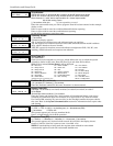
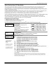
Start Output Device Mapping by pressing *79 while in Data Programming Mode.
∗
∗∗
∗79 Menu Mode
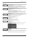
ENTER OUTPUT NO.
00 = QUIT xx
Device Output Number
01-18 = VISTA-20P relays/X-10; 01-08, 17, 18 = VISTA-15P relays/X-10
[
∗
] to continue; 00 to quit
This is the logical (or reference) relay number as used in the system. Relays and X-10
devices are numbered 01-16; the on-board triggers are numbered 17 and 18 and can be
programmed for inverted output, if required. Use the worksheet on the Programming Form
(printed separately) to organize device numbers.
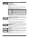
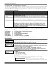
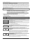
17 OUT NORM LOW
0 = NO 1 = YES 0
Output Normally Low
(prompt appears only for Triggers 17 and 18)
0 = no (standard default); 1 = yes
[
∗
] to continue
Selecting 0 (no) sets the output level normally high (default setting).
Selecting 1 (yes) sets the output normally low.
Output Trigger 17 can be used for resetting 4-wire smoke detectors by connecting it to the
negative power terminal of the smoke detector, selecting 1 at this prompt, and setting as
zone type 54, fire zone reset, in *80 Menu mode.
After entry, display returns to Output Number prompt. Use *80 Menu mode to program
the function of the trigger.
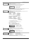
XX OUTPUT TYPE
DELETE 0
Output Type
0 = delete; 1 = relay on 4204/4229 module; 2 = Powerline Carrier device (X-10)
[
∗
] to continue
Select whether this is a relay or a Powerline Carrier (X-10) device.
If Powerline Carrier is selected, go to “A” prompt.
If relay is selected, skip to “B” prompt.
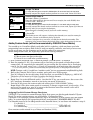
“A”
XX UNIT No.
yy
Unit Number (prompt appears if X-10 is selected)
01-16 = predefined address
[
∗
] to continue
Enter the unit code (set at the device) and press [∗].
The system returns to the Output Number prompt.
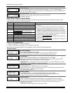
“B”
XX MODULE ADDR
07-15 yy
Module Address (prompt appears if relay is selected)
07-15 = predefined address
[
∗
] to continue
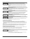
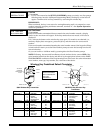
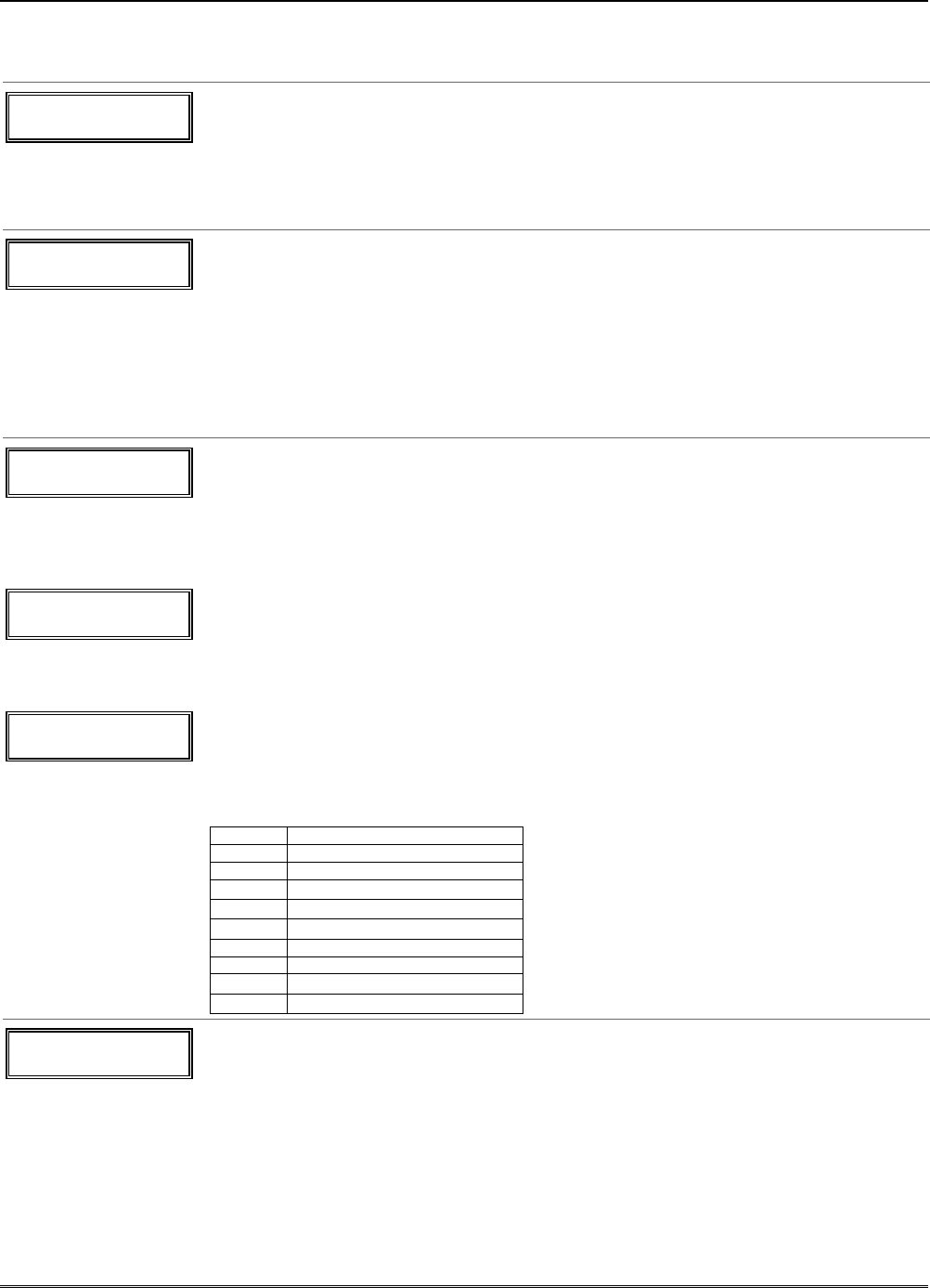
Enter the predefined address for this module as listed below. Make sure the module’s DIP
switches are set to the selected address.
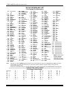
Module Addresses
Address Module † These addresses apply to VISTA-20P only.
07 1st 4229 (with zones 09-16)
08 2nd 4229 (with zones 17-24)
09
†
3rd 4229 (with zones 25-32)
10
†
4th 4229 (with zones 33-40)
11
†
5th 4229 (with zones 41-48)
12 1st 4204
13 2nd 4204
14
†
3rd 4204
15
†
4th 4204
XX REL POSITION
1-4 zz
Relay Position
1-4 = relay position
[
∗
] to continue
This is the actual (or physical) relay number with respect to the Relay Module upon which
it is located. For 4204 modules, relay numbers are 1-4. For 4229 modules, relay numbers
are 1-2.
The system returns to the Output Number prompt for programming the next device.
Menu Mode Programming
5-9