


About Output Device Programming (*79/*80 Menu Mode)
Output Devices: The VISTA-20P system supports up to 16 relays and/or Powerline Carrier devices
(X-10 devices) plus 2 built-in trigger outputs in any combination. These 18 “outputs”
are assigned to system-wide output numbers (01-18). Use *79 Menu Mode to assign
output numbers and map them to device addresses.
The VISTA-15P supports 8 relays and 2 built-in trigger outputs (total 10 outputs).
Output Functions: The system also provides installer-defined output functions, which can be assigned to
any of the physical outputs. Therefore, the action of any one of the outputs can be
based on as many of these functions as desired. This lets a single relay or X-10 device
perform many functions.
The controls support up to 48 output functions.
Use *80 Menu Mode to define output functions.
Relays and output devices are not recommended for life safety applications.
NOTE: When navigating the *79 and *80 menus: The [
✱
] key is used to accept an entry and advance to
the next prompt. The [#] key is used to revert back to the last question to check or change an entry. Press
[
✱
] to go forward again.
Programming Output Devices
1. Use *79 Menu Mode to assign module and output numbers and map them to device addresses.
NOTE: You must map output devices using *79 Menu Mode before you can use *80 menu Mode.
2. Use *80 Menu Mode to create output definitions, which control the output devices, if desired.
3. Use *81 Zone List Menu mode to define zone lists for use with output devices if the device action is
based on more than one zone.
• To program a device for manual activation (user code + [#] [7] / [#] [8] + 2-digit device number) or for
scheduled automatic activation, simply map the device using *79 Menu mode.
• To program a device to automatically activate upon a system event (or function key), use *79 Menu mode to
map the device, then use *80 Menu mode to define the automated device action.
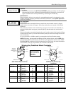
*79 Menu Mode: Output Device Mapping
Use this menu to assign Relay Module device addresses and specific relay numbers, and Powerline Carrier
unit numbers. The system is based on predefined module addresses for 4204 and 4229 modules. Refer to the
table shown at the “Module Address” prompt on the next page and set the modules’ addresses (via module
DIP switches) accordingly.
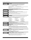
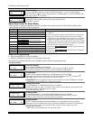
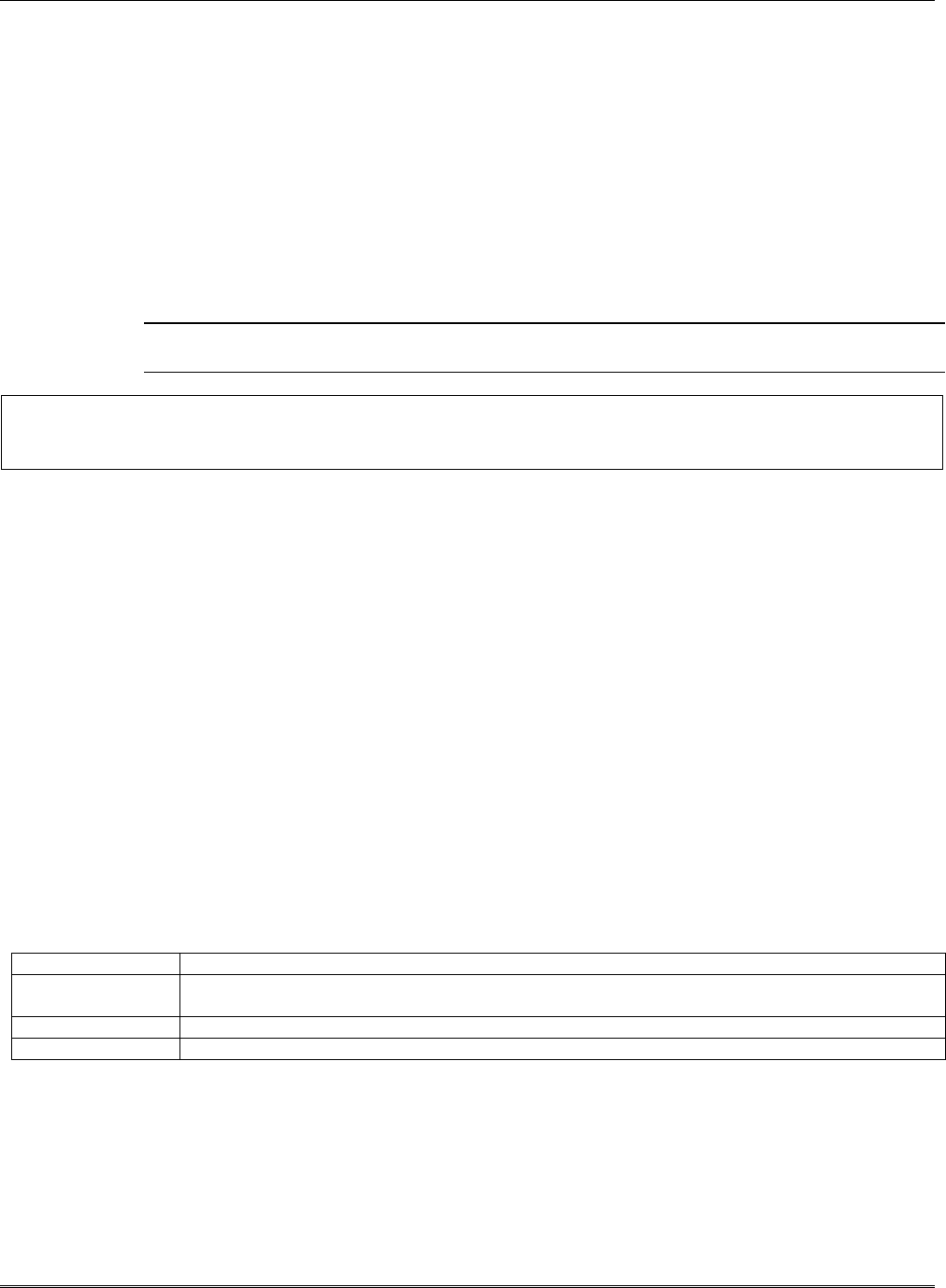
The following table shows how these outputs are identified.
Output Identification
This output… is identified by…
Relays the Relay Module’s device address and the relay position on that module (i.e. the physical relay
number, 1-4, on that module).
X-10 Device a house ID (entered in data field *27) and the unit number of the device.
Built-in Outputs the output number assigned, 17 for Trigger 1 and/or 18 for Trigger 2.
Installation and Setup Guide
5-8