


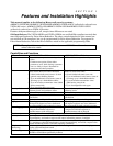

Smoke Detector Notes
•
••
• Fire Verification (zone type 16): The control panel will “verify” a fire alarm by
resetting the smoke detectors after the first alarm trigger, and then waiting 90 seconds
for a second alarm trigger. If the smoke detector or thermostat does not trigger again,
the control will disregard the first trigger, and no alarm signal will occur. This feature
eliminates false alarms due to electrical or physical transients.
SIA Installations: If using fire verification on zones other than zone 1, UL Fire Alarm
Listed relay accessories must be used to reset power as described in the Power Reset
paragraph above.
• The zone 1 alarm current supports only one smoke detector in the alarmed state.
•
••
• Clean Me Option: If enabled (field *174 = 1; *56 zone programming, response time
prompt = 3), certain ESL smoke detectors send “clean me” reports as appropriate. If
used, the maximum number of detectors is reduced to 10 (not standard 16). Refer to the
ESL documentation included with the smoke detector for information regarding
compatibility with the clean-me option.
• Do not use 4-wire smoke detectors on zone 1.
+
+
2000
OHMS
EOLR
HEAT
DETECTOR
RED
EOL
POWER
SUPERVISION
RELAY MODULE
A77-716B.
USE N.O.
CONTACT,
WHICH CLOSES
WHEN POWER
IS APPLIED.
VIOLET
AUX PWR
OUTPUT
TERMINALS
5
4
+
BLK
+
4_wiresmk-007-V0
TO ZONE TERM. ( )
TO ZONE TERM. ( )
RELAY
CONTACT OPENS
MOMENTARILY UPON
FIRE ALARM RESET
PROGRAM
RELAY
AS ZONE
TYPE 54
(FIRE ZONE
RESET)
4-WIRE SMOKE
OR COMBUSTION
DETECTOR
N.C.
N.O.
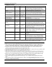
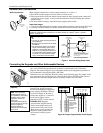
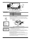
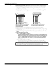
Figure 9a. 4-Wire Smoke Detector Using Relay for Power Reset
+
2000
OHMS
EOLR
HEAT
DETECTOR
RED
VIOLET
AUX PWR
5
+
BLK
+
4_wiresmk-008-V0
4-WIRE SMOKE
OR COMBUSTION
DETECTOR
( )
( )
+
TO ZONE TERM. ( )
TO ZONE TERM. ( )
TO OUTPUT 17
PROGRAM OUTPUT 17
FOR "OUT NORM
LOW" = YES IN 79 MENU
MODE AND AS ZONE
TYPE 54 IN
80 MENU MODE
EOL
POWER
SUPERVISION
RELAY MODULE
A77-716B.
USE N.O.
CONTACT,
WHICH CLOSES
WHEN POWER
IS APPLIED.
N.O.
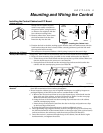
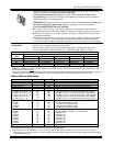
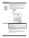
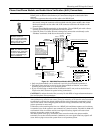
Figure 9b. 4-Wire Smoke Detector Using Output 17 for Power Reset
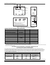
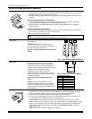
4219/4229 Expansion
Zones
➞
➞
➞
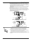
1. Connect each module to the control’s keypad terminals and set the device addresses.
• VISTA-20P: Up to 40 expansion zones using up to 5 Zone Exp. Modules.
• VISTA-15P: Up to 16 expansion zones using up to 2 Zone Exp. Modules.
2. Connect sensors to the module’s loops. See Figure 8 on the following page.
• Use 1000 ohm end-of-line resistors at the end of loops connected to the 4219/4229
modules. (EOLRs used on the control terminals are 2000 ohms.)
•
Expansion zones have normal response time (300–500 msec), except zone connected
to each module’s loop “A,” which can be set for fast response (10–15 msec).
3. If using relays with the 4229, connect the desired field wiring to the unit's relay contact
terminals.
Mounting and Wiring the Control
2-7