


THX9321 PRESTIGE
®
2.0 AND THX9421 PRESTIGE
®
IAQ 2.0 WITH EIM
68-0311—01 6
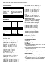
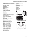
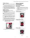
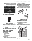
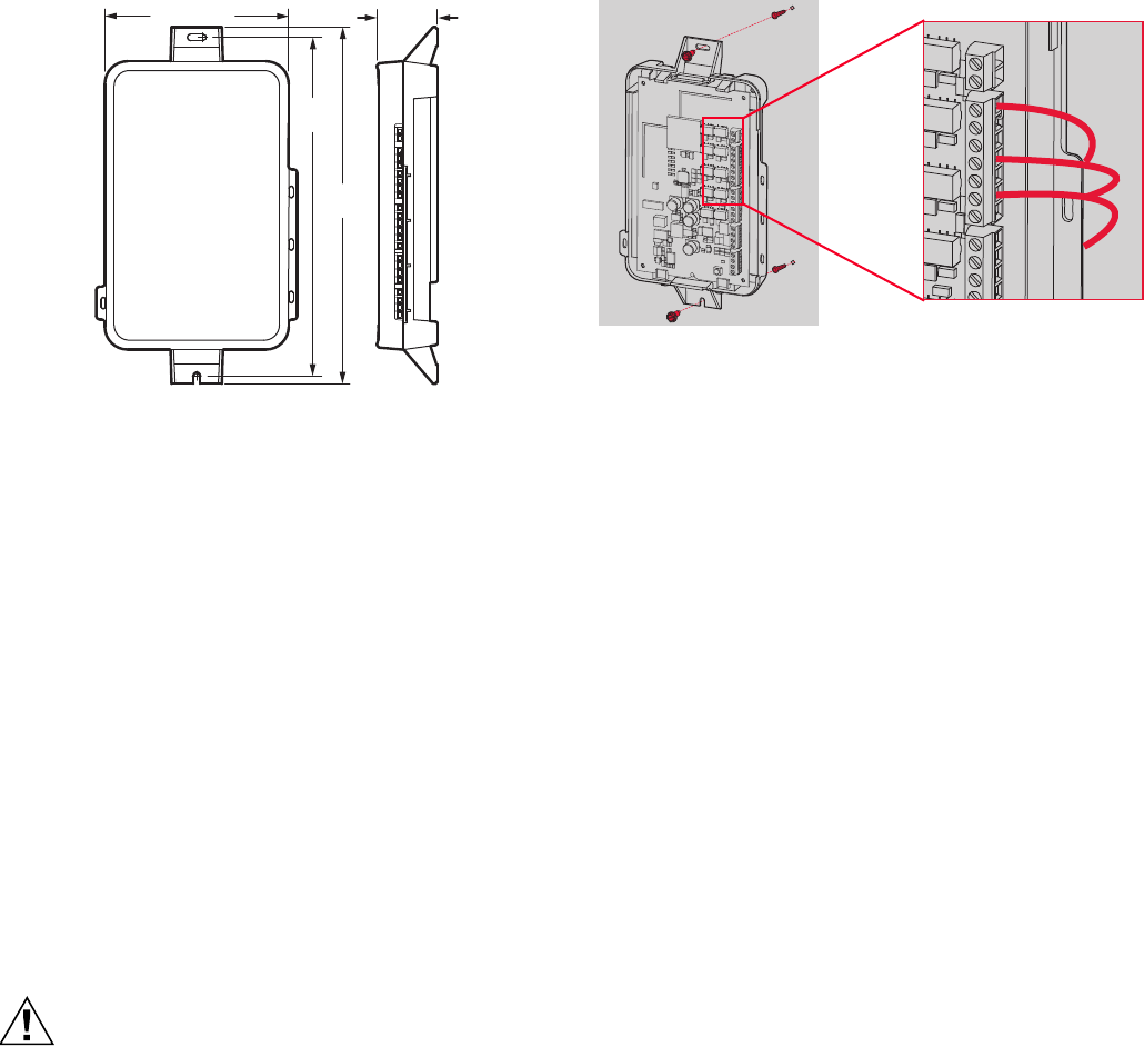
Fig. 3. Dimensions of Equipment Interface Module in in.
(mm).
SYSTEM INSTALLATION
When Installing this Product...
1. Read these instructions carefully. Failure to follow the
instructions can damage the product or cause a hazard-
ous condition.
2. Check the ratings given in the instructions to make sure
the product is suitable for your application.
3. Installer must be a trained, experienced service
technician.
4. After completing installation, use these instructions to
verify the product operation.
Installing Equipment Interface
Module (if used)
If no Equipment Interface Module is used, skip to “Selecting
Thermostat Location” beginning on page 8.
CAUTION
Electrical Hazard.
Can cause electrical shock or equipment damage.
Disconnect power before wiring.
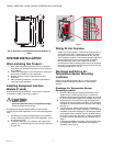
The Equipment Interface Module (EIM) can be mounted
vertically on the HVAC equipment or on a wall in the equipment
room.
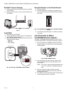
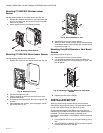
1. Use screws & anchors as appropriate for the mounting
surface. Mount the EIM near the HVAC equipment, or on
the equipment itself.
2. To wire the EIM, strip 1/4” insulation, then insert wires
(see Fig. 4). For wiring diagrams, see “Wiring” beginning
on page 102.
Fig. 4.
Wiring 24 Vac Common
• Single-Transformer System—Connect the common side of
the transformer to the C screw terminal of the EIM. Leave
the metal jumper wires in place between R, Rc, and RH.
• Two-Transformer System—Connect the common side of the
cooling transformer to the C screw terminal of the EIM.
Remove the metal jumper wire between Rc and Rh.
Connect the hot side of heating transformer to Rh and leave
the jumper wire between R and Rc and connect the hot side
of cooling transformer to R or Rc.
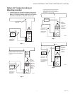
Discharge and Return Air
Temperature Sensor Mounting
Locations
Refer to the guidelines below and Fig. 5–9 for mounting
locations of the Discharge and Return Air Temperature
Sensors.
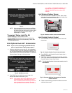
Discharge Air Temperature Sensor
Mounting Location
1. Mount the Discharge Air Temperature Sensor on the
supply duct in a location where the air is mixed well.
Mount the Discharge Air Temperature Sensor out of sight
of the A-Coil/Heat Exchanger when possible. See Fig. 5.
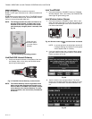
2. When possible, mount the Discharge Air Temperature
Sensor upstream of a Steam Humidifier, a Fan Powered
Humidifier or a Dehumidifier that is ducted to the supply.
See Fig. 6–7.
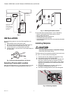
3. If space does not allow a Discharge Air Temperature
Sensor upstream of a Steam Humidifier or Fan Powered
Humidifier, mount the Discharge Air Temperature Sensor
downstream of the Humidifier. See Fig. 6. When setting
the Delta T Limits (see “Set Delta T Limits” on page 53),
be sure to consider the affect that the humidifier has on
Delta T.
4. If a Bypass Humidifier is installed, mount the Discharge
Air Temperature Sensor downstream of the Bypass
Humidifier. See Fig. 8–9.
M33331
4-53/64 (123)
8-7/8
(225)
9-11/32
(237)
1-19/32
(41)
MCR32388
MCR32389
R
C
Y
Y2
G
L
W
O/B
W2
AUX1
W3
AUX2