


S7999B, S7999C SOLA LOCAL OPERATOR INTERFACE
9 65-0303—05
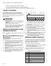
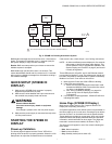
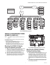
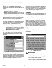
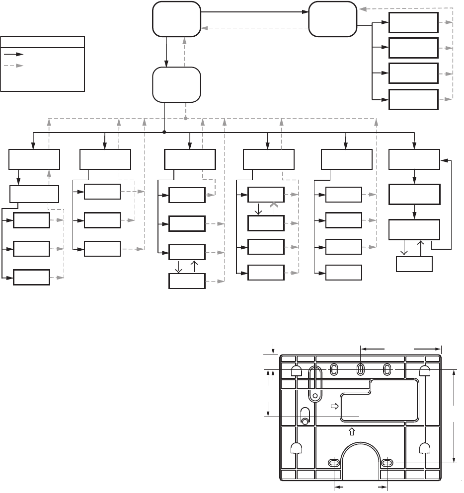
Fig. 8. S7999B display page flow.
INSTALLATION INSTRUCTIONS
(S7999C OI DISPLAY)
NOTE: For S7999B OI Display installation instructions, see
page 4.
The S7999C display is used for individual boiler monitoring.
The S7999C is mounted:
• onto a panel using the wallplate provided.
• from the front into a panel cutout (7.6 in. W X 5.4 in. H)
using 4 #6-32 screws and nuts (provided).
• From behind into a panel cutout (5.45 in. W X 4.3 in. H)
using 4 #6-32 screws, nuts and 4 standoffs (provided).
Mounting the S7999C OI Display
using the wallplate (provided)
1. Select the location to mount the OI display; this could be
a location up to 1000 feet from the SOLA control.
2. Use the device wallplate as a template to mark the loca-
tion of three or four mounting screw holes. See Fig. 9.
3. Drill 3/16 in. holes for mounting the wallplate.
4. Secure the wallplate with three or four #6-32 screws.
5. Bring power and communication wire through the wall
plate and attach to the terminals on the back of the dis-
play before installing the display to the wall plate.
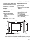
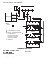
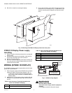
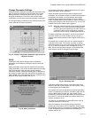
Fig. 9. S7999C wallplate dimensions in in. (mm).
Mounting the S7999C OI Display
directly to the Door Panel
1. Select the location to mount the display.
2. Cut an opening to facilitate mounting the display into the
door panel. See Fig. 1 for the dimensions for mounting
the display from the front of the door. See Fig. 10 for
mounting the display to the back of the door. If desired,
cut a notch so the LEDs will be visible as well. Tear off
templates are also available on the back pages of this
Manual (see Fig. 121 on page 63 and Fig. 122 on page
65).
3. Fit the display into the opening and use the screw holes
in the device as a template to mark the location of the
four mounting screw holes.
HOME
PAGE
SUMMARY
PAGE
M13965
1 2 3 4
SETUP
PROGRAM
MODULE
CLEAN
SCREEN
SYSTEM
CONFIG.
ADVANCED
SETUP
CONFIGURE
Configuration
Groups
Login
Logout
Verify
OPERATION
CH
Login
DHW
DIAGNOSTICS
Diagn.
Test
Burner
Control
Digital
I/O
Analog
I/O
DETAILS
History
Alerts
Diagn.
Analysis
HISTORY
OK
Lockouts
Alerts
Silence
MODULATION
?
SETPOINTS
PUMPS
KEY
BUTTON FLOW
BACK ICON FLOW
HOME ICON ALWAYS TAKES
YOU TO THE HOME PAGE
1-21/32
(42)
1-13/16 (46)
3-13/64
(81)
2-3/4 (70)
M27606
1/2
(13)