


S7999B, S7999C SOLA LOCAL OPERATOR INTERFACE
39 65-0303—05
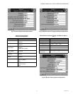
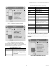
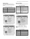
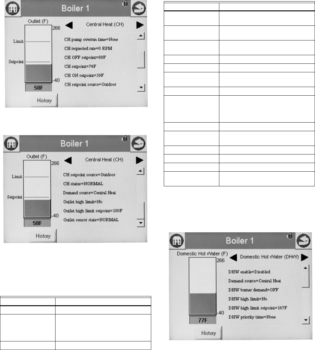
Fig. 73. CH Hydronic Status menu (middle).
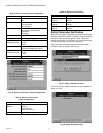
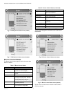
Fig. 74. CH Hydronic Status menu (bottom).
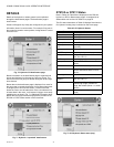
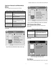
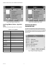
The status data in Table 46 displays first when the DHW
Hydronic heating loop is selected on the Home page. Scrolling
through the status groups eventually shows both.
The bar graph displayed for the CH control loop (hydronic) is
the outlet sensor temperature; for the DHW control loop it is
the DHW sensor temperature. When no analog DHW sensor is
installed (digital switch instead), the inlet sensor temperature is
displayed.
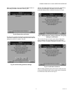
Fig. 75. DHW Hydronic Status menu (top).
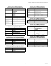
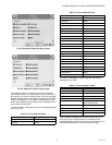
Table 46. DHW Hydronic Status.
Data Comment
DHW enable Enabled, Disabled
Demand source Unknown, No source demand, CH,
DHW, Lead Lag, CH frost protection,
DHW frost protection, No demand due
to burner switch
DHW burner demand On or Off
DHW high limit Temp setting between -40 °F to 266 °F
(-40 °C to 130 °C)
DHW high limit
setpoint
Temp setting between -40 °F to 266 °F
(-40 °C to 130 °C)
DHW priority override
time
0-600 seconds
DHW pump On or Off
DHW pump demand On or Off
DHW pump overrun
time
Running overrun time for DHW pump
(seconds)
DHW requested rate RPM or %
DHW sensor state None, Normal, Open, Shorted,
Outside high range, Outside low
range, Not reliable (None = no outlet
sensor)
DHW OFF setpoint Setpoint plus hysteresis
DHW setpoint Temp setting between -40 °F to 266 °F
(-40 °C to 130 °C)
DHW ON setpoint Setpoint minus hysteresis
DHW setpoint source Normal, TOD, Outdoor reset
DHW status Disabled, Normal, Suspended
DHW temperature DHW temperature (same as bar
graph)
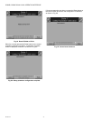
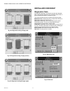
Table 46. DHW Hydronic Status. (Continued)
Data Comment