


S7999B, S7999C SOLA LOCAL OPERATOR INTERFACE
65-0303—05 42
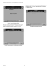
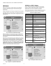
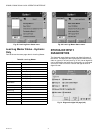
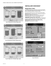
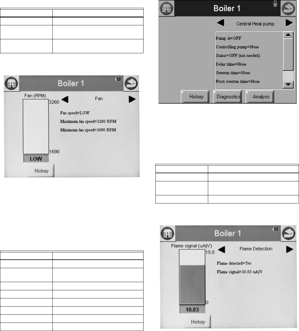
The bar graph displayed for this status is the fan speed.
Fig. 83. Control Fan Status menu.
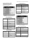
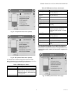
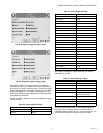
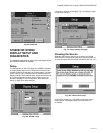
Hydronic Pump Status
Table 51 displays the status page data for this example,
Central Heat pump in the R7910A. Screens available for DHW,
Boiler, System, Aux1 and Aux2 will be the same if that pump is
configured.
Fig. 84. Hydronic CH pump status menu.
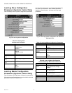
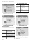
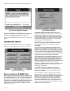
Flame Detection Status
The status data shown in Table 52 is displayed for flame
detection in the R7910A or R7911.
The bar graph displayed for this status is the flame signal.
Fig. 85. Flame Detection Status menu.
NOTE: This same status is also displayed for burner control
status. A separate status group is defined to provide a
bar graph of the flame signal.
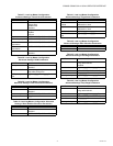
Table 50. Control Fan Status.
Data Comment
Fan speed % or RPM (current fan speed)
Maximum fan speed Setpoint of maximum fan speed (% or
RPM)
Minimum fan speed Setpoint of minimum fan speed (% or
RPM)
Table 51. Hydronic CH Pump Status.
Data Comment
CH Pump On or Off
Controlling Pump
Terminal
Pump A, B, or C
Status On, Off, or Not Used
Delay time Duration of delay time
Overrun time Duration of overrun time
Frost overrun time Duration of frost overrun time
Idle days Number of days idle
Cycle count Number of cycles
Table 52. Flame Detection Status.
Data Comment
Flame detected Yes or No
Flame signal Flame signal strength (same as bar
graph)
Pilot test hold Off or hold