


S7999B, S7999C SOLA LOCAL OPERATOR INTERFACE
65-0303—05 20
A new control is visible when configuration and status data is
gathered from it. This collection procedure takes a few
minutes. The control is marked as “Unknown” when no
configuration information exists. Normally, control configuration
data collection only needs to be performed when the control is
initially installed. However, a re synchronization is necessary
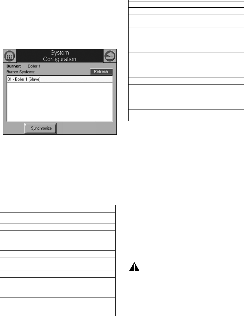
after the OI Display is reset. See Fig. 36.
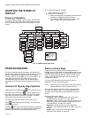
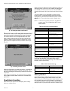
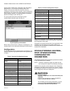
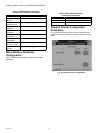
The user presses the Synchronize button to begin
synchronization with the control. See Fig. 36.
Fig. 36. System synchronization.
Status of the synchronization is reflected in the dialog box. The
synchronization can be aborted by selecting the Cancel button.
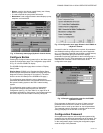
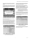
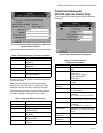
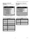
Configuration
The SOLA Control can be configured from the OI Display. The
control configuration is grouped into the functional groups seen
in Table 5.
Most of this configuration is performed by either the contractor/
installer or at Honeywell. Each functional group is displayed on
the Configuration menu page.
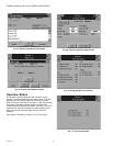
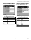
Parameters in functional groups that are not applicable for the
installation can be ignored. In some cases, features in a
functional group are disabled by default and are enabled when
needed for the installation.
R7910A HYDRONIC CONTROL,
R7911 STEAM CONTROL
CONFIGURATION
PARAMETERS
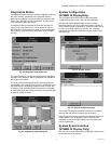
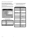
The following pages list the configuration parameters available
for the R7910A or R7911 installed.
NOTE: Individual Configuration pages may differ from this
text as features are added or amended by Honeywell.
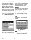
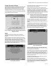
A password is required to make changes to the Configuration
Parameters. The SOLA Control will be in a Lockout 2 “waiting
for safety data verification” as received or will go to a Lockout 2
when changes are made to the safety data.
WARNING
Explosion Hazard.
Improper configuration can cause fuel buildup and
explosion.
Improper user operation may result in PROPERTY
LOSS, PHYSICAL INJURY or DEATH.
The OI Display used to change parameters, must be
attempted by only experienced and/or licensed
burner/boiler operators and mechanics.
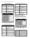
Table 5. Functional Configuration Groups.
Hydronic Control Steam Control
System Identification and
Access
Steam Identification and
Access
CH - Central Heat Steam Configuration
Outdoor Reset Modulation Configuration
DHW - Domestic Hot Water Pump Configuration
DHW Storage
DHW Plate
Warm Weather Shutdown
Demand Priority
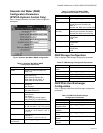
Modulation Configuration Statistics Configuration
Pump Configuration Stack Limit
Statistics Configuration Annunciation Configuration
High Limit Burner Control Interlocks
Stack Limit Burner control Timings and
Rates
Delta T Limits
T-Rise Limit
Heat Exchanger High Limit
Anti-condensation Burner Control Flame Failure
Frost Protection
Configuration
System Configuration
Annunciation Configuration Fan Configuration
Burner Control Interlocks Lead Lag Configuration
Burner Control Timings and
Rates
Burner Control Ignition
Burner Control Flame Failure
System Configuration
Fan Configuration
Sensor Configuration
Lead Lag Slave
Configuration
Lead Lag Master
Configuration
Table 5. Functional Configuration Groups.
Hydronic Control Steam Control