S7999B, S7999C SOLA LOCAL OPERATOR INTERFACE
65-0303—05 12
STARTING THE S7999C OI
DISPLAY
Power-up Validation
The Home page will appear and the “Power” LED will be on
continuously and the “COM” LED will be blinking when the
device is properly powered and communicating to the Sola
Control.
The “COM” LED exists for I/O traffic.
1. Make sure the LED is blinking.
2. If the LED is not blinking:
a. Make sure the proper connections have been made
between the display and the Sola Control.
b. See “Wiring (S7999C OI Display)” on page 10 for
proper wiring of the display connections.
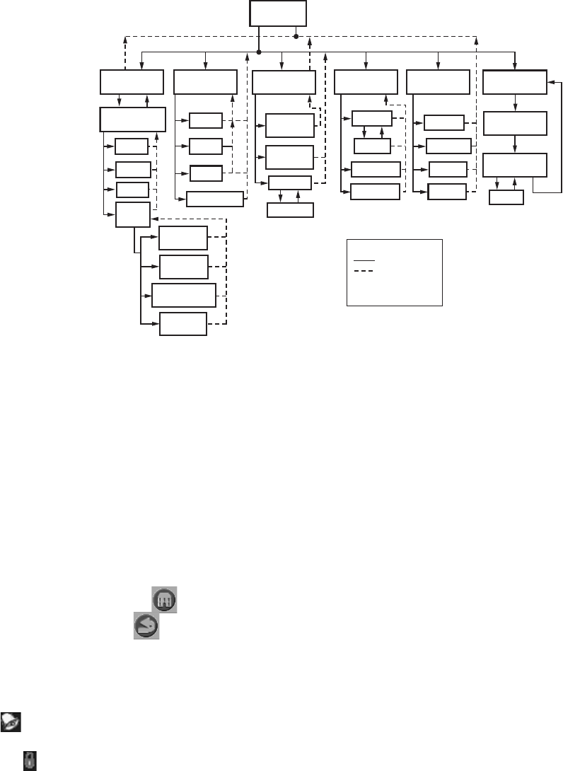
Fig. 13. S7999C display page flow.
PAGE NAVIGATION
The Sola OI Displays present information and options in a
paged manner. Pages are displayed in a tree structure in which
the user navigates up and down to arrive at the desired
Function (see Fig. 8 for S7999B or Fig. 13 for S7999C). The
page descriptions are provided below so that you can
understand the purpose of each and view the selections,
parameters, and information that is available or required on
each.
Common OI Display Page Symbols
Most pages have a Home button in the top-left corner of
the screen and a Back button in the top-right corner of
the screen. The Home button returns the user to the Home
page and terminates any operation in progress. The Back
button returns the user to the previous page.
Two other icons may be noticed near the boiler name.
A bell will be displayed if the system is in Lockout that
reset will be required.
A padlock will be shown on screens that require a password
to change the parameter. An unlocked padlock indicates the
password has been entered to change the parameter.
Status or Home Page
A status (summary) page (Fig. 14) is displayed when the
S7999C display is connected. This status page appears on the
S7999B when the Sola control icon is pressed on the “Home”
page. The status page displays the current condition of the
burner control and displays some of the more important
configuration settings.
The boiler name associated with the burner control is
displayed in the title on the status page.
NOTE: When the burner control has no boiler name defined,
Modbus address is used to identify the boiler.
The initial status page displayed contains summary status
information as shown in Fig. 14. Any status information not
applicable for the installation is grayed/blanked out on the
screen.
Buttons on this screen include:
• Configure: used to configure the burner control (see
“Configure Button” on page 13 for more details).
• Operation: used to perform daily or frequent functions with
the burner control, such as setpoint adjustment, etc. See
“Operation Button” on page 18 for details.
• Diagnostic: used to view burner control diagnostic
information (see “Diagnostics Button” on page 19 for more
details).
• Details: used to view burner control detail status
information (see “Details” on page 38).
HOME
PAGE
M29774
LOGIN
CONFIGURE
CONFIGURATION
GROUPS
LOGOUT
VERIFY
DISPLAY
SETUP
OPERATION
CH
LOGIN
DHW
DIAGNOSTICS
DIAGNOSTIC
TEST
BURNER
CONTROL
DIGITAL I/O
ANALOG I/O
PROGRAM
MODULE
CLEAN
SCREEN
SYSTEM
CONFIGURATION
ADVANCED
SETUP
DETAILS
HISTORY
ALERTS
DIAGNOSTIC
ANALYSIS
HISTORY
OK
LOCKOUTS
ALERTS
SILENCE
MODULATION
SETPOINTS
PUMPS
?
KEY
BUTTON FLOW
BACK ICON FLOW
HOME ICON ALWAYS
TAKES YOU TO THE
HOME PAGE
ANNUNCIATION


