


S7999B, S7999C SOLA LOCAL OPERATOR INTERFACE
45 65-0303—05
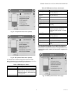
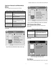
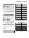
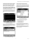
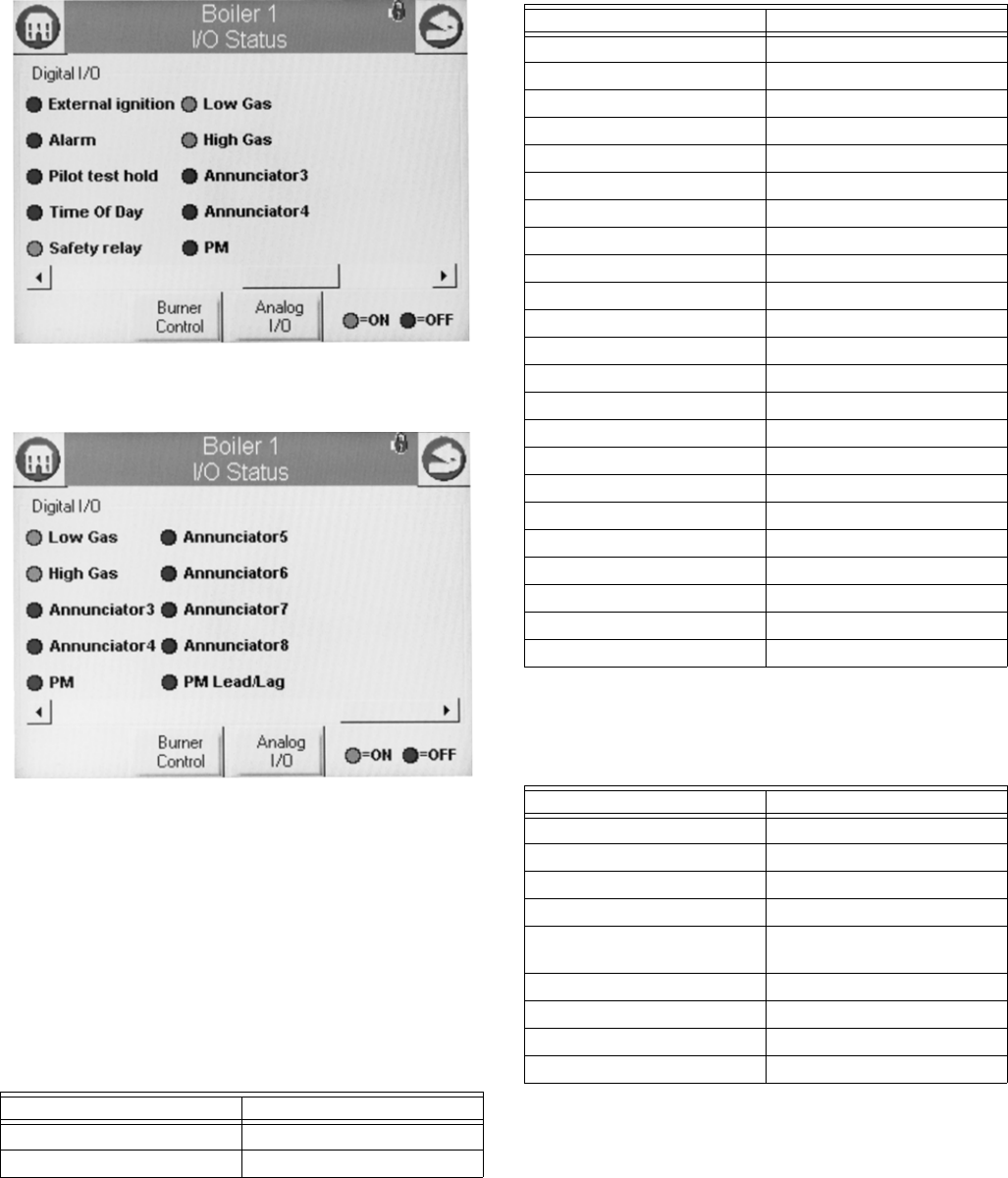
Fig. 92. Diagnostic digital I/O page (center).
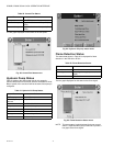
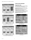
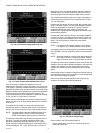
Fig. 93. Diagnostic digital I/O page (right).
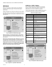
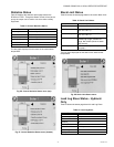
Temperature sensors or pressure sensors also display the
current sensor state, (i.e., whether there is a fault condition or
the sensor is in a normal monitoring state). The user can toggle
between displaying the control digital and analog I/O (the initial
display is the digital I/O). The Digital or Analog button on the
bottom of the diagnostic page changes the I/O displayed to the
type indicated by the button.
The following data is displayed on the control diagnostics page
(see Fig. 91–93).
“On” status is indicated by a green LED and “Off” status is
indicated by a red LED.
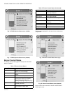
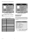
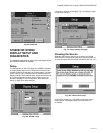
Analog I/O data is displayed as bar charts depicting the I/O
level (see Fig. 94). Analog I/O that is not enabled for the
installation displays a blank I/O level. To see all analog I/O, use
the horizontal scroll bar to move the view left and right.
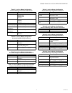
Table 57. Control Digital I/O Data.
Data Comment
Pump A On/Off
Pump B On/Off
Pump C On/Off
Blower/HSI On/Off
Pilot valve On/Off
Main valve On/Off
Load Control Input On/Off
STAT On/Off
Pre-ignition interlock On/Off
Interlock On/Off
External ignition On/Off
Alarm On/Off
Pilot test hold On/Off
Time Of Day On/Off
Safety relay On/Off
Low Gas On/Off
High Gas On/Off
Annunciator 3 On/Off
Annunciator 4 On/Off
PM On/Off
Annunciator 5 On/Off
Annunciator 6 On/Off
Annunciator 7 On/Off
Annunciator 8 On/Off
PM Lead/Lag On/Off
Table 58. Control Analog I/O Data.
Data Comment
Outlet
Inlet If enabled
Firing rate % or RPM
Flame signal V
Fan speed RPM (if applicable). Should
match with firing rate.
Domestic Hot Water If enabled
Stack If enabled
Outdoor If enabled
Header If enabled
Table 57. Control Digital I/O Data.
Data Comment