STRYKER VAV USER GUIDE
62-2030—01 22
14. FLOW BALANCING
The flow balancing view is used to balance a controller that is
programmed with a standard VAV application. Based on the
version of the VAV application and its features, the following
operations can be performed on the view.
• Flow pressure zero calibration
• Two point calibration
• K factor calibration
• Heating coil water flow calibration.
• Pre-requisites
• The controller must be online.
• The controller must be in a commissioned state.
• VAV Zone Terminal Single Duct must be selected as the
Application Type and Air Balance Supported must be
selected.
NOTE: Note: The selections must be done before down-
loading the program to the controller.
• Select the Reheat Valve Override Supported option to
calibrate the reheat valve.
• Select the Peripheral Heat Valve Override Supported
option to calibrate the peripheral heat valve.
To flow balance:
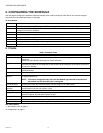
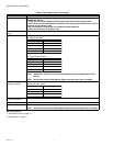
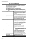
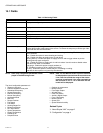
14.1 Fields
Table 13. Flow Balancing Fields.
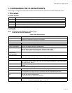
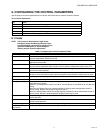
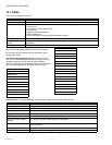
Flow pressure zero calibration
To start zero balancing:
Click Start Zero Balancing.
The damper is completely closed. If any flow pressure is
detected, that value is considered to be the flow pressure
offset. After the completion of zero balancing, the device
mode is set to automatic operation.
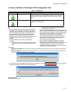
Step Action
1 On the Nav palette, browse to Station > Config > Drivers> LonNetwork > LonDevice.
or
Browse to Station > Config > Drivers> BacnetNetwork > BacnetDevice.
2 Right-click ControlProgram and select Views > Flow Balancing View. The Flow Balancing View appears on
the right pane.
You can type the values into the following fields.
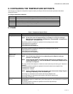
Name Description
Actuator Travel Time The actuator travel time is the time required by the actuator to travel from 0% to 100% open or 100% to
0% open. This time interval depends on the actuator type and can vary from 0 to 500 seconds.
K Factor This field allows you to manually change the K factor value from 0 to 10000.
Inlet Area Displays the area of the duct. Either a standard diameter can be selected or a custom area can be
entered in this field. The inlet area ranges from 0 to 100 sq.ft.
Measured Flow Displays the actual air flow when measured by the balancer using an accurate device. This field is
editable.
Maximum Flow
Setpoint
This field allows you to set the flow setpoint from 0 to 138850 cfm for maximum flow calibration and k
factor calibration. The controller seeks stable flow and when it is reached, it allows you to set the
calibration source value.
Minimum Flow
Setpoint
This field allows you to set the flow setpoint value from 0 to 138850 cfm. You must set the flow setpoint
less than the maximum value to obtain minimum flow calibration. The controller seeks stable flow and
when it is reached, it allows you to set the calibration source value.
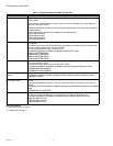
Re-heat Valve
Override
This field allows to override the value of the reheat valve in an application built for the reheat valve. This
field is visible when the Reheat Valve Override Supported feature is selected in the Details View of
the Control Program.
Peripheral Heat
Valve Override
This field allows to override the value of the peripheral heat valve in an application built for the
peripheral heat valve. This field is visible when the Peripheral Heat Valve Override Supported feature
is selected in the Details View of the Control Program.
Device Mode Displays the current device mode. This is a non-editable field.
Damper Position Displays the current damper position. This is a non-editable field.
Sensed Flow Displays the actual air flow that is measured by a pressure sensor. This field is non-editable.
Flow Pressure Displays the current flow pressure. This field is non-editable.