


STRYKER VAV USER GUIDE
19 62-2030—01
Related Topics
“1. About Stryker VAV” on page 2
“2. Configuration” on page 4
“3. Configuring the Outputs” on page 5
“4. Configuring the Inputs” on page 8
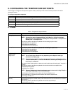
“6. Configuring the Temperature Setpoints” on page 11
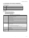
“8. Configuring the Control Parameters” on page 15
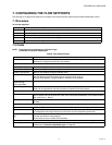
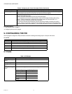
11. CONFIGURING THE CUSTOM WIRING
Use this page to customize the wiring/pin assignment of IOs for an Stryker VAV device on the LON network.
The custom wiring is allowed only for the inputs and outputs parameters that are configured.
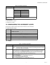
To configure custom wiring:
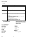
11.1 Fields
None
RELATED TOPICS
“1. About Stryker VAV” on page 2
“2. Configuration” on page 4
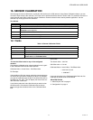
12. ALARM VIEW
Use this page to view errors logged by the Stryker VAV device.
This action can be performed only when the device is in the
online mode.
The controller must be in a commissioned state.
NOTE: Note: The controller is capable of tracking and
reporting several types of errors.
Groups of errors of the same type are also reported as an
alarm by the controller using nvoAlarmH.
This means that several different errors of the same type will
be reported as a single alarm.
For Example: Multiple sensors connected to the controller
may read invalid values and the controller will log individual
errors for each sensor.
However a single 'SensorFailure' alarm will be reported.
This page displays all the errors that are currently active and
reported by the controller.
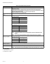
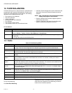
To view alarms:
Step Action
1 From the left pane of the VAV Configuration Wizard, select Custom Wiring.
2 To reassign inputs or outputs to different pins, simply select the input/output in the relevant drop-down.
3
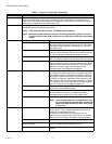
Click Terminal Overlay Diagram to generate the terminal overlay diagram.
NOTE: Note: The terminal overlay diagram is formatted to match the size of the terminal overlay
present on the controller. Only 6 characters will be displayed in the generated terminal over-
lay diagram.
This allows you to print the Terminal Overlay to use it on the relevant controller.
4 Click Wiring Diagram to see the wiring between inputs and outputs. This wiring diagram shows how the
controller is connected with the external inputs and outputs.
5 Click Undo All to revert to the last saved settings.
6 Click Finish to save settings to station.
Step Action
1 From the Nav menu, choose Station > Driver > LON network > Stryker VAV device.
2 Right-click the device and choose Views > Alarms View from device items. The Alarm screen appears.