


STRYKER VAV USER GUIDE
62-2030—01 18
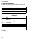
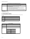
Setpoint Configure the setpoints to be used by the loop in different occupancy modes. Configure the
minimum and maximum reset values to be used and the corresponding reset sensor values.
Reset value to be added to the setpoint is calculated by the controller as a value between min max
reset values in proportion to the reset sensor value.
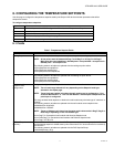
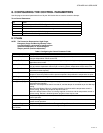
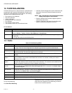
Control Parameters Parameters that affect the output and the loop behavior can be configured. Below are the
configurable parameters and its descriptions.
NOTE: If derivative time is set to zero, it disables derivative action.
NOTE: Modulating output threshold value for activating the Auxiliary output can be con-
figured to control the auxiliary output based on the value of PID loops modulating
output.
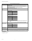
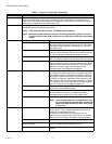
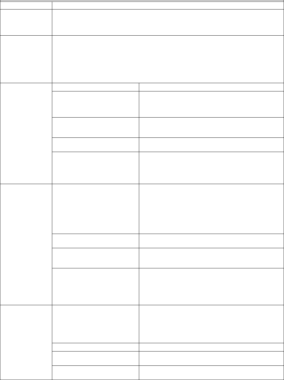
Control Parameters Configurable Parameters Description
Throttling range This is the proportional change in the sensed variable
required to change the control output from 0 to 100 percent.
This needs to be configured in the engineering unit of the
main input sensor
Integral time This determines the integral gain of the PID loop. The
greater the time in seconds, the less the integral change per
second. A setting of 0 eliminates the integral function.
Derivative time Determines the derivative gain in a PID loop. The greater the
time in seconds, the greater the derivative effect per second
PID action Direct Acting or Reverse Acting selection determines the
behavior of the loop output. In a direct acting control loop the
output increases as the input sensor value rises above the
setpoint. In a reverse acting control loop the output
increases as the input falls below the setpoint.
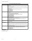
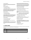
Control Parameters Aux DO action This determines the Aux DO behavior. The Aux output can
be configured for either continuous or intermittent operation.
This selection applies to occupied and standby modes only.
Unoccupied is always intermittent. In continuous operation
the output is continuous, regardless of the operation of the
other outputs of the loop. In intermittent operation the output
is on only when the modulating output of the loop is greater
than 0 or at least one of the staged outputs is on.
Modulating control for Aux This option allows the Aux DO to be controlled based on the
value of the loops modulating output.
Modulating output threshold for Aux Modulating output threshold value for controlling the
Auxiliary output. The Aux DO is activated if the PID
modulating output is greater than the threshold value
Aux output minimum off time The auxiliary digital output minimum off time.
NOTE: When staged outputs are configured this value
must be configured to be less than (Cycler and
stager interstage minimum on time - Aux output
run on time).
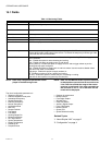
Control Parameters Aux output run on time The auxiliary digital output run-on time. A value of 0 disables
the run-on time. This is typically used when the AuxDo is
configured for intermittent operation.
For example, If the AuxDO is controlling the fan, this
parameter can be used to keep the fan running for certain
duration after the cooling or heating process has stopped.
Minimum off time This is the minimum off time for the staged outputs
Cycler and stager interstage
minimum on time
This is minimum amount of time a lower numbered stage
must be on before the next stage can turn on.
Minimum on time This is the minimum on time for the Aux DO and staged
outputs
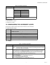
Table 11. Accessory Loop Fields. (Continued)
Name Definition