STRYKER VAV USER GUIDE
21 62-2030—01
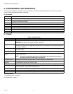
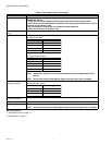
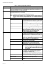
Sylkbus Alarm: The Sylkbus communication alarm occurs
when the communication link between the Sylk sensor and
the controller is lost or when the Sylk sensor is configured with
the wrong address.
To communicate successfully with an Stryker VAV device,
TR71/TR75 devices must be configured with the address 1.
To communicate successfully with an Stryker VAV device,
C7400S sensors must be configured with the address 8.
5Node disabled Error: The node disabled error is reported
when the control execution is disabled.
For example, this error is reported when the controller is
commanded to manual mode.
RELATED TOPICS
“1. About Stryker VAV” on page 2
“2. Configuration” on page 4
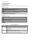
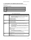
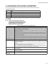
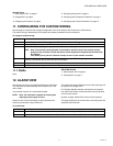
13. DIAGNOSTICS
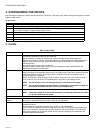
Use this page to test the outputs of an Stryker VAV device in
manual mode. This action can be performed with the device in
online mode. The device must be in downloaded state.
The Diagnostics screen displays:
• All configured Digital Outputs to command ON/OFF
• All configured Analog Outputs to command the values
between 0 to 100%
• The values that are sensed (currently) at the outputs
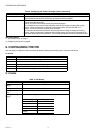
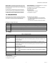
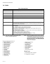
To diagnose an Stryker VAV device:
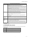
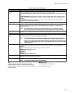
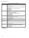
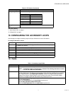
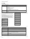
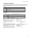
13.1 Fields
Table 12. Diagnostic Fields.
RELATED TOPICS
“1. About Stryker VAV” on page 2
“2. Configuration” on page 4
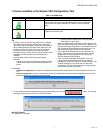
Step Action
1 From the Nav menu, choose Station > Driver > LON network > AscLonVAV device.
2 Right-click the device and choose Views > Diagnostics from device items. The Diagnostics screen appears.
3 Enter information in the available fields.
4 Click Refresh to reset the settings.
5 Click Set to set the output values for diagnosis.
Name Definition
Name Displays the configured parameter names.
Modulating Output
Diagnostics
The number of Modulating Outputs depends on the outputs configured in the application.
Current Value: Displays the value of the modulating output as read from the controller. This
field is non-editable.
Edit Value: Enter the value that the output must be commanded to. The range is 0-100 %.
Binary Output Diagnostics The number of Binary Outputs depends on the outputs configured in the application.
Current Value: Displays the value of the modulating output as read from the controller. This
field is non-editable.
Edit Value: Select ON or OFF.
Set Click Set. The controller is set to 'Manual' control and the commanded output values are written
to the controller.
NOTE: Note: If the controller is in Auto mode, click Set to set the controller to Manual
mode.
Auto Refresh Select the Auto Refresh checkbox to automatically refresh the output values every 30 seconds.
Refresh Select the Refresh to refresh the output values, only when the device is in manual mode.
Current Mode Displays the current mode of the device.