


STRYKER VAV USER GUIDE
62-2030—01 16
RELATED TOPICS
“1. About Stryker VAV” on page 2
“4. Configuring the Inputs” on page 8
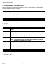
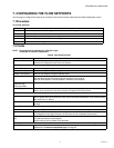
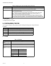
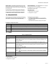
9. CONFIGURING THE PID
Use this page to configure the PID parameters for both the heating and cooling loops in a Stryker VAV device.
To set PID:
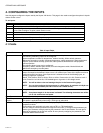
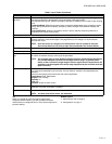
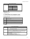
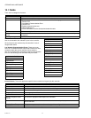
9.1 Fields
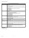
Flow Tracking Offset Represents the flow tracking offset value used when FlowType is configured as FlowTracking. This
offset is added to the value of nviFlowTrack to determine the flow setpoint.
Terminal load calculation Enables you to perform the terminal load calculation. You have the option to select 0 or 1 in the
Terminal load calculation field.
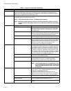
Select 0 to use the conventional zone terminal load calculation.
The conventional zone terminal load calculation uses the PID output of heating and cooling
controls. When the controller is switched to the heating mode, the Terminal load is ? 0.
Select 1 to use the CZS zone terminal load calculation.
The CZS zone terminal load calculation uses the proportional output of heating and cooling
controls. When the controller is switched to the heating mode, the Terminal Load continues to
report both heating and cooling demand. The terminal load absolute value is truncated at 100%.
Table 9. Configuring the Control Parameter Fields. (Continued)
Name Definition
Step Action
1 From the left pane of the VAV Configuration Wizard, select PID.
2 Enter information in the available fields.
3 Click Next to display the Accessory Loops page.
4 Click Undo All to revert to the last saved settings.
5 Click Finish to save settings to station.
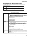
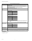
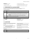
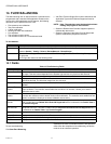
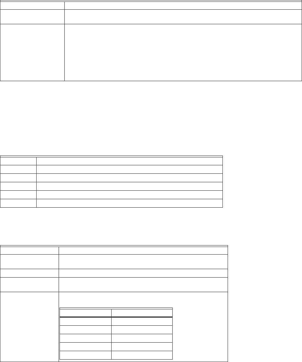
Table 10. PID Names.
Name Definition
Cooling Throttling
Range
Value must be between 2 to 30 DDF.
Cooling Integral Time Value must be between 0 to 9000 sec.
Cooling Derivative
Time
Value must be between 0 to 9000 sec.
Heating Throttling
Range
Value must be configured based on reheat configuration.
Reheat Type TR (DegF)
modulating 5
1 stage 3
2 stage 4
3 stage 7
4 stage 8