


b. Amount of venting required. Due to the many
different combinations that can be used when con-
structing venting, the number of vent sections
required can only be determined by the installer.
1-99 9 21322L
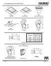
GC150 SERIES DIRECT VENT GAS APPLIANCE
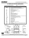
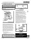
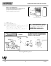
Figure 6
Exterior Wall Hole
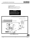
Figure 7
Interior Wall Shield
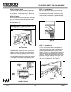
Note: Exterior wall thickness must be a min-
imum of 4" to a maximum of 23
1
⁄2”.
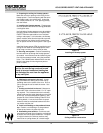
Figure 8
Venting Through the Wall
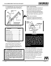
Note: Horizontal runs will require the use of
one Vent Support (VS4) for every 3' of vent.
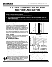
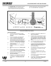
4. Venting through the wall. Horizontal venting
must terminate within the shaded area shown in
Figure 5 on the previous page. For example, if
your vertical rise is the minimum one foot, venting
can terminate anywhere between 16 inches and 3
feet.
The last section of vent may require cutting, depend-
ing upon wall thickness and appliance location. The
end of the vent must penetrate the exterior wall. Cut
the pipe so the outer vent section extends past the
exterior wall by 1" and the inner vent section extends
past the exterior wall by 2
1
⁄2". See Figure 8.
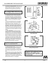
2. Preparing the wall for interior wall shield. A
hole measuring 10" wide X 12" high must be cut
and framed in the exterior wall where venting will
be terminated. If the wall being penetrated is con-
structed of non-combustible material, i.e. masonry
block or concrete, a 9" diameter port is accept-
able.
The hole must be positioned so the vent system
will have a 1/4" rise for every 12" of run AND be
perpendicular to the wall. See Figure 6. The
height of the hole must be located to meet all local
and national codes and not be easily blocked or
obstructed. The minimum height to the top of the
exterior wall hole is 45” from the base of the unit.
This figure will increase by the length of each verti-
cally positioned vent section added to the venting
system.
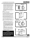
3. Interior Wall Shield. An interior wall shield
must be installed each time the venting system
penetrates a wall. This shield has been designed
to maintain the minimum clearances needed for
the venting system and prevent cold air infiltration.
After the venting hole has been cut and framed,
secure an interior wall shield into position with four
1" fasteners, one in each corner. Bend out the
tabs located on the inner portion of the wall shield
and use a 1/2" screw to secure each tab to the
penetrating pipe. See Figure 7. (1/2" screws are
used to avoid penetrating the inner pipe.)
NOTE: IF THE TERMINATION CAP IS SUR-
ROUNDED BY VINYL SIDING OR IS LOCAT-
ED BELOW A VINYL SOFFIT, A VINYL
SHIELD MUST BE USED TO PREVENT DAM-
AGE TO THE VINYL.