


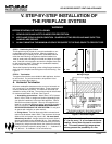

GC150 SERIES DIRECT VENT GAS APPLIANCE
12-98 16 21322K
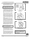
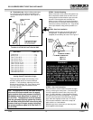
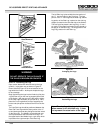
After applying the finishing material, a non-com-
bustible sealant, one-half inch wide maximum, must
be used to close off any gaps at the top and sides
between the fireplace and finishing material to pre-
vent cold air leaks. See Figure 22.
A combustible mantel may be installed at a minimum
of 42 inches above the base of the appliance (See
page 4 “Fireplace Dimensions”).
Figure 22
Location of Panels
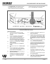
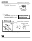
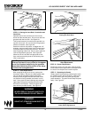
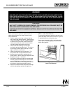
STEP 10 - Screen Removal
After removing the hood and lower panel, you are
able to remove the protective fire screen. Simply
remove the screws(4) located in each corner of the
screen, lift it out and set aside. See Figure 23. (The
screen must be replaced prior to operating this appli-
ance.)
Figure 23
Screen Removal
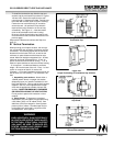
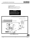
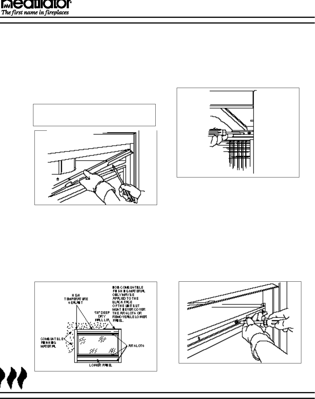
STEP 11 - Glass Removal
To begin removal of the glass, loosen,but do not
remove the four sheet metal screws located at the
lower portion of the glass. Next, unscrew the four
screws located on the top portion of the glass as
shown in Figure 24. Be sure to hold the glass to pre-
vent it from falling out once the screws have been
loosened. Remove the metal retaining strip which is
positioned along the upper edge of the glass. See
Figure 25. Gently tilt the glass towards yourself and
lift it out of the bottom track. See Figure 26.
Figure 24
Glass Removal
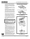
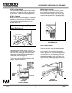
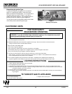
STEP 8 - Attaching Hood
The hood is to be located just above the glass panel.
Four screws are visible just inside the upper section
of the fireplace. Remove these screws, position the
hood and screw into place. See Figure 21
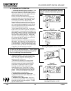
STEP 9 - Finishing
When finishing the face of the appliance, combustible
material may be brought up to the sides of the appli-
ance, but must never overlap onto the black metal.
The black metal may be covered with non-com-
bustible material only.
Note: You cannot cover any of the panels
on this appliance, as this may create a fire
hazard. See Figure 22.
Figure 21
Hood Placement