


2-99 6 21322L
INSTALLATION AND REPAIR SHOULD BE DONE BY A QUALIFIED SERVICE PERSON. THE APPLIANCE
SHOULD BE INSPECTED BEFORE USE AND AT LEAST ANNUALLY BY A QUALIFIED SERVICE PERSON.
MORE FREQUENT CLEANING MAY BE REQUIRED DUE TO EXCESSIVE LINT FROM CARPETING, BED-
DING MATERIAL, ETC. IT IS IMPERATIVE THAT CONTROL COMPARTMENTS, BURNERS AND CIRCU-
LATING AIR PASSAGEWAYS OF THE APPLIANCE BE KEPT CLEAN.
DUE TO HIGH TEMPERATURES, THE APPLIANCE SHOULD BE LOCATED OUT OF TRAFFIC AND AWAY
FROM FURNITURE AND DRAPERIES.
WARNING!
THIS APPLIANCE MAY ONLY USE THE DIRECT VENT CHIMNEY SYSTEM DESIGNED FOR USE
WITH THE UNIT AND MUST NOT BE CONNECTED TO A CHIMNEY FLUE SERVICING A SEPA-
RATE SOLID FUEL OR GAS FUEL BURNING APPLIANCE.
GC150 SERIES DIRECT VENT GAS APPLIANCE
IV. PRE-INSTALLATION PREPARATION
A. GAS PRESSURE
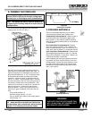
C. FIREPLACE LOCATIONS AND
SPACE REQUIREMENTS
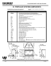
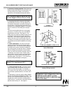
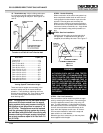
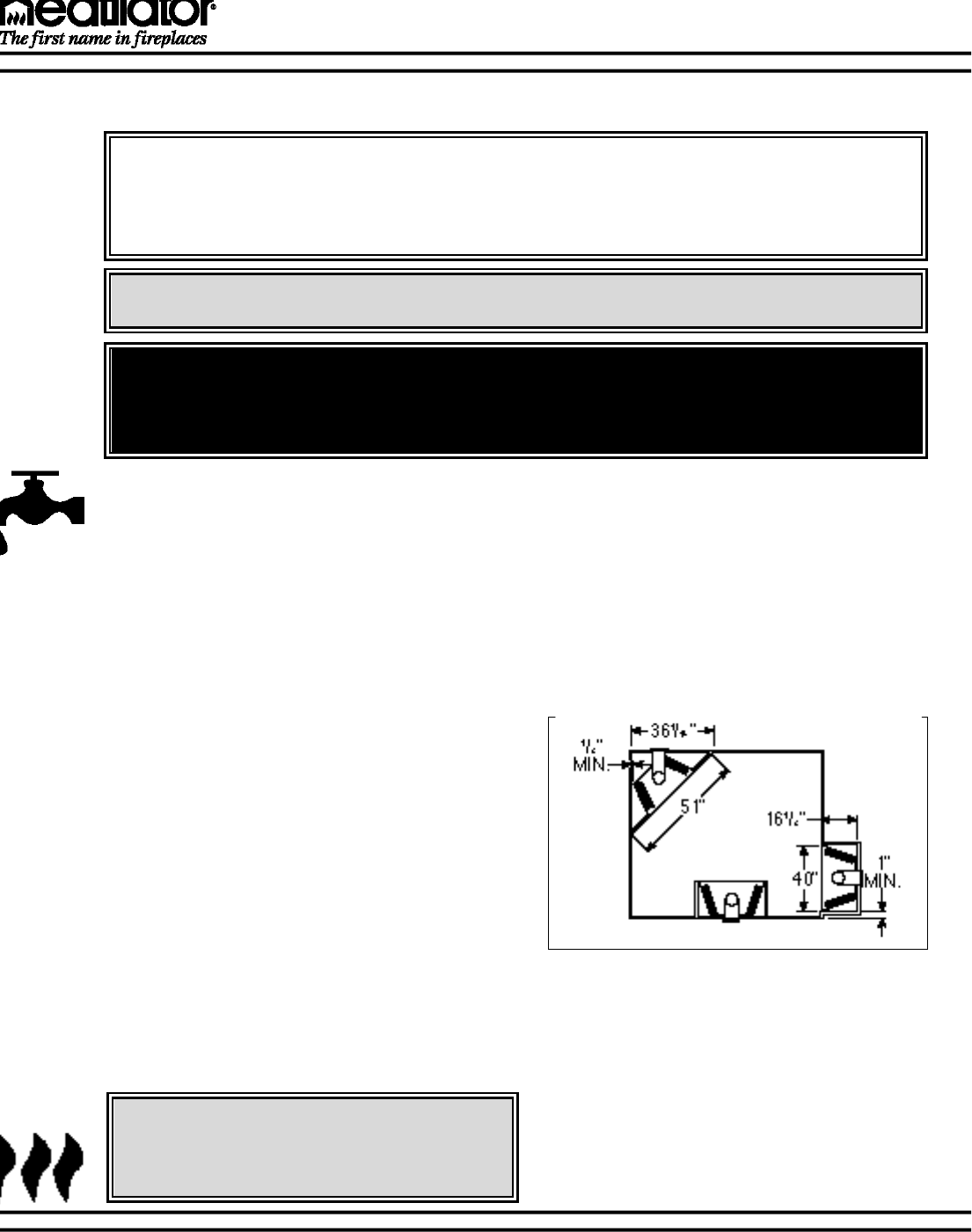
This appliance may be installed along a wall, across a
corner or use an exterior chase. The GC150 Series
may be installed at a height level with the floor, or it
can be raised up from the floor to enhance its visual
impact. Figure 1 illustrates a variety of ways the
appliance may be located in a room. These appli-
ances are also certified for installation in a bedroom
or bed/sitting room in the U.S.
For natural gas, the minimum inlet gas supply pressure is
4.5 inches water column, and the maximum inlet gas pres-
sure is 7.0 inches water column, for the purpose of input
adjustment. Input rate is 22,500 Btu/hr. For propane gas,
the inlet gas supply pressure must be at least 11.0 inches
water column and a maximum 14.0 inches water column.
(See CKP Natural Gas to Propane Gas Conversion Kit
installation instructions.)
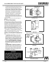
A 1/8" NPT plugged tapping is provided on the gas control
valve, near the outlet to the main burner immediately
upstream of the gas supply connection to the appliance,
accessible for a test gage connection .
Optimum manifold pressure is 3.5 inches water column for
natural gas and 10.5 inches water column for propane gas.
B. HIGH ALTITUDE INSTALLATION
For U.S. installation, units are tested and approved for ele-
vations from 0-2000 feet.
When installing this unit at an elevation above 2000 feet,
United States codes require a decrease of the input rating
by changing the existing burner orifice to a smaller size.
Input should be reduced 4 percent for each 1000 feet
above sea level. Check with the local gas utility for proper
orifice size identification. This unit uses a .093in. /2.36
mm. orifice size on natural gas versions and a .056 in./1.42
mm. orifice size on propane gas converted versions.
Consult your local gas company for assistance in determin-
ing the proper orifice for your location or refer to ANSI
Z223.1-latest edition, Appendix F.
Figure 1
Fireplace Locations and Clearances
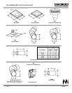
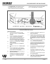
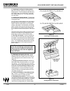
D. CLEARANCES
The following clearances to combustibles must be
maintained: Minimum clearances to the top standoffs
of the unit - 0", floor - 0", back - 1/2", sides - 1/2", top
of the hood to ceiling - 30". Minimum clearances to
venting are as follows: Horizontal runs require a 3"
minimum air space on the top and a 1" minimum air
space on the sides and bottom of the vent section.
Vertical rise sections require a 1" minimum air space
completely around the vent sections.
CAUTION:
DO NOT EXPOSE THE UNIT TO THE
ELEMENTS (SUCH AS RAIN, ETC.).